1-4
Section 1
SAFETY
053430; 01/11
1.1
General Safety Precautions
1.1.1 Safety-Alert Signs
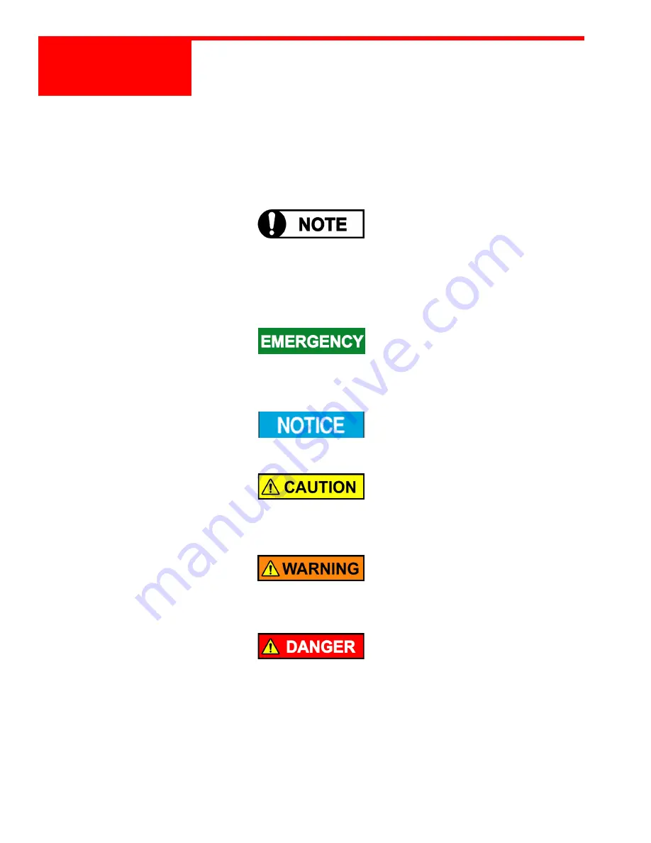
This manual contains Safety-Alert Signs, as defined below, which must be followed
to
reduce the possibility of improper servi ce damage to the equipment or personal
injury. Read and follow all Safety-Alert Signs included in this manual.
NOTE defines an operating procedure,
condition, etc. which is essential to
highlight that contains useful or
important information.
EMERGENCY is used for the identification of safety equipment,
first aid, or emergency egress locations.
NOTICE used to convey safety information on labels and signs.
CAUTION is indicative of a potentially hazardous situation which,
if not avoided, may result in minor or moderate injury.
Potentially hazardous situations that could result in death
or serious injury are indicated by the word WARNING.
DANGER indicates an imminently hazardous situation which,
if not avoided, will result in death or serious injury.
Summary of Contents for MSP445
Page 1: ...OPERATIONS PARTS MANUAL MSP445 RIDING TROWEL REVISION 05 2018 MANUAL PART 053430 ...
Page 17: ...1 1 053430 01 11 Section 1 SAFETY Section 1 SAFETY ...
Page 29: ...2 1 053430 01 11 SECTION 2 OPERATIONS Section 2 OPERATIONS ...
Page 38: ...2 10 SECTION 2 OPERATIONS 053430 01 11 Notes ...
Page 39: ...3 1 053430 01 11 SECTION 3 SERVICE Section 3 SERVICE ...
Page 60: ...3 22 SECTION 3 SERVICE 053430 01 11 Notes ...
Page 61: ...4 1 053430 1 11 4 1 053430 1 11 Section 4 PARTS Section 4 PARTS ...
Page 74: ...4 14 053430 1 11 MSP445 Frame Pre 9 2013 048838 MSP445 Frame Post 9 2013 060891 Frame Design ...
Page 75: ...4 15 053430 1 11 4 6 Illustration Fuel System 1 2 4 5 8 9 10 11 11 10 12 13 6 7 14 ...
Page 77: ...4 17 053430 1 11 4 7 Illustration Electrical System 2 1 3 3 3 5 6 7 8 3 4 11 12 13 ...
Page 83: ...4 23 053430 1 11 4 10 Illustration Pitch Control Assembly 2 4 7 8 ...
Page 87: ...4 27 053430 1 11 4 12 Illustration Engine System 1 2 3 4 ...
Page 91: ...4 31 053430 1 11 4 14 Illustration Driveline System 13 5 3 8 6 9 14 10 10 1 7 2 12 11 ...
Page 93: ...4 33 053430 1 11 4 15 Illustration Throttle Control System 1 2 4 7 3 6 5 ...
Page 95: ...4 35 053430 1 11 4 16 Illustration Oil Drain System 2 1 ...
Page 101: ...4 41 053430 1 11 4 20 Illustration Right Hand Spider Assembly 1 5 2 4 11 10 7 6 9 8 ...
Page 103: ...4 43 053430 1 11 4 21 Illustration Left Hand Spider Assembly 1 3 2 4 7 5 8 9 10 6 11 ...
Page 111: ...4 51 053430 1 11 4 25 Illustration Rear View Identification and Marking Decals 12 11 6 2 ...
Page 115: ...4 55 053430 1 11 4 27 Illustration Accessory Non standard Items 2 1 ...
Page 117: ...4 57 053430 1 11 4 28 Illustration Tools Service 1 2 ...


