2-4
SECTION 2
OPERATIONS
053430; 01/11
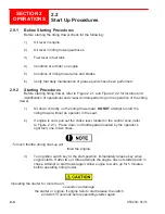
2.9.1 Before Starting Procedures
Before starting the riding trowel check for the following:
1) Oil level in engine.
2) Oil level in riding trowel gearboxes.
3) Fuel level in fuel tank.
4) Condition of air filter on engine.
5) Condition of riding trowel arms and blades.
6) Verify that daily maintenance of grease points have been performed.
2.9.2 Starting Procedures
Before starting riding trowel, refer to Figure 2.2.1 and Figure 2.2.2 for location and
identification of operational and visual controls pertaining to the operation of the riding
trowel.
1) Sit down correctly on the riding trowel seat.
DO NOT
attempt to start the
riding trowel without an operator in the seat.
2) If engine is cold, pull out the choke lever located in the control zone (refer
to Figure 2.2.1). Press down on throttle pedal (located by the operator’s
right foot) one to two times.
To much throttle during start-up will
flood the engine.
3) Turn ignition switch key to the start-position, immediately release key when
engine starts. If after two or three attempts the engine has not started push in
choke. Attempt to start trowel again. Allow engine to warm up for 5 minutes
before operating riding trowel.
Operating the starter for more than 5
seconds can damage
the starter or engine. If engine fails to start release the switch
and wait 15 seconds before operating starter again.
2.2
Start Up Procedures
Summary of Contents for MSP445
Page 1: ...OPERATIONS PARTS MANUAL MSP445 RIDING TROWEL REVISION 05 2018 MANUAL PART 053430 ...
Page 17: ...1 1 053430 01 11 Section 1 SAFETY Section 1 SAFETY ...
Page 29: ...2 1 053430 01 11 SECTION 2 OPERATIONS Section 2 OPERATIONS ...
Page 38: ...2 10 SECTION 2 OPERATIONS 053430 01 11 Notes ...
Page 39: ...3 1 053430 01 11 SECTION 3 SERVICE Section 3 SERVICE ...
Page 60: ...3 22 SECTION 3 SERVICE 053430 01 11 Notes ...
Page 61: ...4 1 053430 1 11 4 1 053430 1 11 Section 4 PARTS Section 4 PARTS ...
Page 74: ...4 14 053430 1 11 MSP445 Frame Pre 9 2013 048838 MSP445 Frame Post 9 2013 060891 Frame Design ...
Page 75: ...4 15 053430 1 11 4 6 Illustration Fuel System 1 2 4 5 8 9 10 11 11 10 12 13 6 7 14 ...
Page 77: ...4 17 053430 1 11 4 7 Illustration Electrical System 2 1 3 3 3 5 6 7 8 3 4 11 12 13 ...
Page 83: ...4 23 053430 1 11 4 10 Illustration Pitch Control Assembly 2 4 7 8 ...
Page 87: ...4 27 053430 1 11 4 12 Illustration Engine System 1 2 3 4 ...
Page 91: ...4 31 053430 1 11 4 14 Illustration Driveline System 13 5 3 8 6 9 14 10 10 1 7 2 12 11 ...
Page 93: ...4 33 053430 1 11 4 15 Illustration Throttle Control System 1 2 4 7 3 6 5 ...
Page 95: ...4 35 053430 1 11 4 16 Illustration Oil Drain System 2 1 ...
Page 101: ...4 41 053430 1 11 4 20 Illustration Right Hand Spider Assembly 1 5 2 4 11 10 7 6 9 8 ...
Page 103: ...4 43 053430 1 11 4 21 Illustration Left Hand Spider Assembly 1 3 2 4 7 5 8 9 10 6 11 ...
Page 111: ...4 51 053430 1 11 4 25 Illustration Rear View Identification and Marking Decals 12 11 6 2 ...
Page 115: ...4 55 053430 1 11 4 27 Illustration Accessory Non standard Items 2 1 ...
Page 117: ...4 57 053430 1 11 4 28 Illustration Tools Service 1 2 ...


