3-4
SECTION 3
SERVICE
053430; 01/11
3.3
Drive Belt
3.3.0 Drive Belt Maintenance
The drive belts MUST be free from oil and
foreign contaminants to prolong life.
3.3.1 To Replace The Drive Belt:
1) The MSP445 is equipped with a spare belt located inside the belt guard.
2) Place the trowel on a flat, level surface with the blades pitched flat.
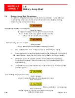
3) Disconnect the battery. Refer to Figure 3.3.1.
4) Use a M6x1.0x40 mm bolt to spread apart the pulleys to allow slack in the belt
and remove it from the lower and upper pulleys. Refer ti Figure 3.3.3.
5) Replace new belt in opposite order of removal.
6) Reconnect the battery.
3.3.2 To Add Drive Belt:
1) Place the trowel on a flat, level surface with the blades pitched flat.
2) Disconnect the battery. Refer to Figure 3.3.1.
3) Remove battery and plate assembly by removing (4) 5/16-18 x 1 bolts. Refer
to Figure 3.3.1
4) Disconnect and remove u-joint assembly by removing (4X) 1/4-20x3/4 socket
head round screws and 1/4 split lock washers on the driveshaft hub closest to
driven pulley. Refer to Figure 3.3.2.
5) Apply one drop of blue Loctite No. 242 to the (4X) 1/4-20x3/4 socket head
round screws and reassemble with 1/4 split lock washers in opposite order of
disassembly.
6) Install battery plate assembly with one drop blue Loctite No. 242 on the
5/16-18 x 1 bolts.
7) Reconnect the battery.
Summary of Contents for MSP445
Page 1: ...OPERATIONS PARTS MANUAL MSP445 RIDING TROWEL REVISION 05 2018 MANUAL PART 053430 ...
Page 17: ...1 1 053430 01 11 Section 1 SAFETY Section 1 SAFETY ...
Page 29: ...2 1 053430 01 11 SECTION 2 OPERATIONS Section 2 OPERATIONS ...
Page 38: ...2 10 SECTION 2 OPERATIONS 053430 01 11 Notes ...
Page 39: ...3 1 053430 01 11 SECTION 3 SERVICE Section 3 SERVICE ...
Page 60: ...3 22 SECTION 3 SERVICE 053430 01 11 Notes ...
Page 61: ...4 1 053430 1 11 4 1 053430 1 11 Section 4 PARTS Section 4 PARTS ...
Page 74: ...4 14 053430 1 11 MSP445 Frame Pre 9 2013 048838 MSP445 Frame Post 9 2013 060891 Frame Design ...
Page 75: ...4 15 053430 1 11 4 6 Illustration Fuel System 1 2 4 5 8 9 10 11 11 10 12 13 6 7 14 ...
Page 77: ...4 17 053430 1 11 4 7 Illustration Electrical System 2 1 3 3 3 5 6 7 8 3 4 11 12 13 ...
Page 83: ...4 23 053430 1 11 4 10 Illustration Pitch Control Assembly 2 4 7 8 ...
Page 87: ...4 27 053430 1 11 4 12 Illustration Engine System 1 2 3 4 ...
Page 91: ...4 31 053430 1 11 4 14 Illustration Driveline System 13 5 3 8 6 9 14 10 10 1 7 2 12 11 ...
Page 93: ...4 33 053430 1 11 4 15 Illustration Throttle Control System 1 2 4 7 3 6 5 ...
Page 95: ...4 35 053430 1 11 4 16 Illustration Oil Drain System 2 1 ...
Page 101: ...4 41 053430 1 11 4 20 Illustration Right Hand Spider Assembly 1 5 2 4 11 10 7 6 9 8 ...
Page 103: ...4 43 053430 1 11 4 21 Illustration Left Hand Spider Assembly 1 3 2 4 7 5 8 9 10 6 11 ...
Page 111: ...4 51 053430 1 11 4 25 Illustration Rear View Identification and Marking Decals 12 11 6 2 ...
Page 115: ...4 55 053430 1 11 4 27 Illustration Accessory Non standard Items 2 1 ...
Page 117: ...4 57 053430 1 11 4 28 Illustration Tools Service 1 2 ...


