3-18
SECTION 3
SERVICE
053430; 01/11
3.8
Battery Jump Start
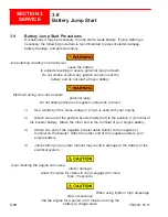
3.9 Battery Jump Start Procedures
Occasionally it may be necessary to jump start a weak battery. If jump starting is
necessary the following procedure is recommended to prevent starter damage,
battery damage, and personal injury.
Jump starting a battery incorrectly can
cause the battery
to explode resulting in severe personal injury or death.
Do not smoke or allow any ignition sources near the
battery and do not start a frozen battery.
Electrical arcing can cause severe
personal injury.
Do not allow positive and negative cable ends to touch.
1) Use a battery of the same voltage (12V) as is used with your engine.
2) Attach one end of the positive booster cable (red) to the positive (+) terminal of
the booster battery. Attach the other end to the terminal of your engine battery.
3) Attach one end of the negative booster cable (black) to the negative (-)
terminal on the booster. Attach the other end of the negative cable to your
engine
battery.
4) Jump starting in any other manner may result in damage to the battery or the
electrical
system.
Over cranking the engine can cause
starter damage.
Allow 5 minutes for starter to cool if engaged for more
than 15 seconds.
When using lights or high amperage
draw accessories,
idle the engine for a period of 20 minutes to bring the
battery to charge state.
Summary of Contents for MSP445
Page 1: ...OPERATIONS PARTS MANUAL MSP445 RIDING TROWEL REVISION 05 2018 MANUAL PART 053430 ...
Page 17: ...1 1 053430 01 11 Section 1 SAFETY Section 1 SAFETY ...
Page 29: ...2 1 053430 01 11 SECTION 2 OPERATIONS Section 2 OPERATIONS ...
Page 38: ...2 10 SECTION 2 OPERATIONS 053430 01 11 Notes ...
Page 39: ...3 1 053430 01 11 SECTION 3 SERVICE Section 3 SERVICE ...
Page 60: ...3 22 SECTION 3 SERVICE 053430 01 11 Notes ...
Page 61: ...4 1 053430 1 11 4 1 053430 1 11 Section 4 PARTS Section 4 PARTS ...
Page 74: ...4 14 053430 1 11 MSP445 Frame Pre 9 2013 048838 MSP445 Frame Post 9 2013 060891 Frame Design ...
Page 75: ...4 15 053430 1 11 4 6 Illustration Fuel System 1 2 4 5 8 9 10 11 11 10 12 13 6 7 14 ...
Page 77: ...4 17 053430 1 11 4 7 Illustration Electrical System 2 1 3 3 3 5 6 7 8 3 4 11 12 13 ...
Page 83: ...4 23 053430 1 11 4 10 Illustration Pitch Control Assembly 2 4 7 8 ...
Page 87: ...4 27 053430 1 11 4 12 Illustration Engine System 1 2 3 4 ...
Page 91: ...4 31 053430 1 11 4 14 Illustration Driveline System 13 5 3 8 6 9 14 10 10 1 7 2 12 11 ...
Page 93: ...4 33 053430 1 11 4 15 Illustration Throttle Control System 1 2 4 7 3 6 5 ...
Page 95: ...4 35 053430 1 11 4 16 Illustration Oil Drain System 2 1 ...
Page 101: ...4 41 053430 1 11 4 20 Illustration Right Hand Spider Assembly 1 5 2 4 11 10 7 6 9 8 ...
Page 103: ...4 43 053430 1 11 4 21 Illustration Left Hand Spider Assembly 1 3 2 4 7 5 8 9 10 6 11 ...
Page 111: ...4 51 053430 1 11 4 25 Illustration Rear View Identification and Marking Decals 12 11 6 2 ...
Page 115: ...4 55 053430 1 11 4 27 Illustration Accessory Non standard Items 2 1 ...
Page 117: ...4 57 053430 1 11 4 28 Illustration Tools Service 1 2 ...


