4-2
053430; 1/11
4-2
Section 4
PARTS
053430; 1/11
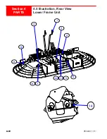
This section contains the illustrated drawings and parts list for help in identifying and/or ordering
replacement parts for your machine. Follow the instructions in the front section of this manual
“Ordering Parts” when ordering replacement parts to insure prompt and accurate delivery.
The Right Hand (RH) and/or Left Hand (LH) orientations are defined from the operator’s view of
sitting on machine (SOM).
All set screws have blue (LOC-TITE™) applied at the
factory. If set screw is removed or loosened for any
reason re-apply blue (LOC-TITE™).
All grease fittings are capped with CAP PLUG GC-5
(AEC PN 015692) to protect the fitting. If cap becomes
missing or damaged replace it as soon as possible.
Anti-Seize is applied at the factory to all drive line coupling,
gear box main and counter shafts and pitch control threaded
rod assemblies. If these parts are disassembled re-apply a light
coat of a graphite based anti-seize.
Factory Service Information
Summary of Contents for MSP445
Page 1: ...OPERATIONS PARTS MANUAL MSP445 RIDING TROWEL REVISION 05 2018 MANUAL PART 053430 ...
Page 17: ...1 1 053430 01 11 Section 1 SAFETY Section 1 SAFETY ...
Page 29: ...2 1 053430 01 11 SECTION 2 OPERATIONS Section 2 OPERATIONS ...
Page 38: ...2 10 SECTION 2 OPERATIONS 053430 01 11 Notes ...
Page 39: ...3 1 053430 01 11 SECTION 3 SERVICE Section 3 SERVICE ...
Page 60: ...3 22 SECTION 3 SERVICE 053430 01 11 Notes ...
Page 61: ...4 1 053430 1 11 4 1 053430 1 11 Section 4 PARTS Section 4 PARTS ...
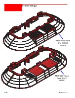
Page 74: ...4 14 053430 1 11 MSP445 Frame Pre 9 2013 048838 MSP445 Frame Post 9 2013 060891 Frame Design ...
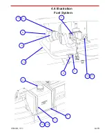
Page 75: ...4 15 053430 1 11 4 6 Illustration Fuel System 1 2 4 5 8 9 10 11 11 10 12 13 6 7 14 ...
Page 77: ...4 17 053430 1 11 4 7 Illustration Electrical System 2 1 3 3 3 5 6 7 8 3 4 11 12 13 ...
Page 83: ...4 23 053430 1 11 4 10 Illustration Pitch Control Assembly 2 4 7 8 ...
Page 87: ...4 27 053430 1 11 4 12 Illustration Engine System 1 2 3 4 ...
Page 91: ...4 31 053430 1 11 4 14 Illustration Driveline System 13 5 3 8 6 9 14 10 10 1 7 2 12 11 ...
Page 93: ...4 33 053430 1 11 4 15 Illustration Throttle Control System 1 2 4 7 3 6 5 ...
Page 95: ...4 35 053430 1 11 4 16 Illustration Oil Drain System 2 1 ...
Page 101: ...4 41 053430 1 11 4 20 Illustration Right Hand Spider Assembly 1 5 2 4 11 10 7 6 9 8 ...
Page 103: ...4 43 053430 1 11 4 21 Illustration Left Hand Spider Assembly 1 3 2 4 7 5 8 9 10 6 11 ...
Page 111: ...4 51 053430 1 11 4 25 Illustration Rear View Identification and Marking Decals 12 11 6 2 ...
Page 115: ...4 55 053430 1 11 4 27 Illustration Accessory Non standard Items 2 1 ...
Page 117: ...4 57 053430 1 11 4 28 Illustration Tools Service 1 2 ...


