4-22
053430; 1/11
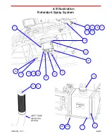
4.9 Parts List
Retardant Spray System
REF PART NO.
DESCRIPTION
QTY NOTES
1
047700
TANK, 6 GALLON PLASTIC
1
2
048921
STRAP, TANK
2
3
012702
TIP, 80°x0.10 GPM BRASS SPRAY
2
4
048909
SWITCH, PUSH BUTTON
1
1
5
048910
BEARING, Ø5/8 NYLON FLANGED SLEEVE
1
1
6
047701
CAP, 3-1/2 VENTED BLACK
1
7
033735
PUMP, SPRAY SYSTEM
1
8
040209
FILTER, SPRAY SYSTEM
1
9
041604
BODY, NYLON CHECK VALVE NOZZLE
2
10
041606
NIPPLE, 1/4 NPT CLOSE PLASTIC
2
11
041624
RETAINER, NYLON SPARY TIP
2
12
047933
ELBOW, 1/4 PUSHLOK X 1/4 NPT PLASTIC
4
13
065244
SCREEN W/ CHECK VALVE (BLUE) 50 MES
2
14
012702
TIP, 80°x0.10 GPM BRASS SPRAY
2
15
047702
FITTING, “L” FUEL 1/4 NIPPLE 90°
1
16
047703
BUSHING, WATER TANK
1
17
016382
SCREW, 10-32x1 ROUND HEAD SLOT MACH
4
18
018072
WASHER, NO. 10 SAE FLAT
4
19
029568
NUT, 10-32 NYLOCK HEX
4
20
040387
ELBOW, 3/8x1/4 90° STREET BRASS
1
21
040388
FITTING, 3/8x1/4 BRASS FM-TO-FM REDUCER
1
22
048652
TEE, PLASTIC 1/4x1/4
1
1
23
010090
WASHER, 5/16 SPLIT LOCK
2
24
010100
NUT, 5/16-18 HEX
2
25
048246
HOSE, 3/8 WATER LINE
7.75
1,2
26
048959
GROMMET, 1/2 RUBBER HOSE
3
1
27
013557
BUSHING, 3/8 X 1/4 BRASS HEX
1
28
047520
ASSEMBLY, SPRAY NOZZLE
-
3
NOTES:
1.
Not shown.
2.
QTY (U/M) shown in feet.
3.
Includes Reference #’s: 3,9,10,11,13
Summary of Contents for MSP445
Page 1: ...OPERATIONS PARTS MANUAL MSP445 RIDING TROWEL REVISION 05 2018 MANUAL PART 053430 ...
Page 17: ...1 1 053430 01 11 Section 1 SAFETY Section 1 SAFETY ...
Page 29: ...2 1 053430 01 11 SECTION 2 OPERATIONS Section 2 OPERATIONS ...
Page 38: ...2 10 SECTION 2 OPERATIONS 053430 01 11 Notes ...
Page 39: ...3 1 053430 01 11 SECTION 3 SERVICE Section 3 SERVICE ...
Page 60: ...3 22 SECTION 3 SERVICE 053430 01 11 Notes ...
Page 61: ...4 1 053430 1 11 4 1 053430 1 11 Section 4 PARTS Section 4 PARTS ...
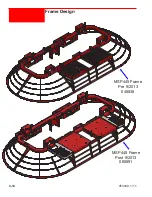
Page 74: ...4 14 053430 1 11 MSP445 Frame Pre 9 2013 048838 MSP445 Frame Post 9 2013 060891 Frame Design ...
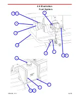
Page 75: ...4 15 053430 1 11 4 6 Illustration Fuel System 1 2 4 5 8 9 10 11 11 10 12 13 6 7 14 ...
Page 77: ...4 17 053430 1 11 4 7 Illustration Electrical System 2 1 3 3 3 5 6 7 8 3 4 11 12 13 ...
Page 83: ...4 23 053430 1 11 4 10 Illustration Pitch Control Assembly 2 4 7 8 ...
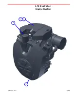
Page 87: ...4 27 053430 1 11 4 12 Illustration Engine System 1 2 3 4 ...
Page 91: ...4 31 053430 1 11 4 14 Illustration Driveline System 13 5 3 8 6 9 14 10 10 1 7 2 12 11 ...
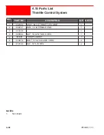
Page 93: ...4 33 053430 1 11 4 15 Illustration Throttle Control System 1 2 4 7 3 6 5 ...
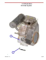
Page 95: ...4 35 053430 1 11 4 16 Illustration Oil Drain System 2 1 ...
Page 101: ...4 41 053430 1 11 4 20 Illustration Right Hand Spider Assembly 1 5 2 4 11 10 7 6 9 8 ...
Page 103: ...4 43 053430 1 11 4 21 Illustration Left Hand Spider Assembly 1 3 2 4 7 5 8 9 10 6 11 ...
Page 111: ...4 51 053430 1 11 4 25 Illustration Rear View Identification and Marking Decals 12 11 6 2 ...
Page 115: ...4 55 053430 1 11 4 27 Illustration Accessory Non standard Items 2 1 ...
Page 117: ...4 57 053430 1 11 4 28 Illustration Tools Service 1 2 ...

