background image

34 


Summary of Contents for BUFFALO 24"

Page 1: ... Machinery Limited Hangar 5 New Road Hixon Stafford ST18 0PJ United Kingdom Tel 44 0 1889 271503 Fax 44 0 1889 271321 sales turfmech co uk www turfmech co uk For Allett spare parts Tel 44 0 1889 272092 or 272093 Fax 44 0 1889 272084 sales allett co uk www allett co uk ...

Page 2: ......

Page 3: ...ATTENTION THIS SYMBOL MEANS BE ALERT YOUR SAFETY IS INVOLVED READ THIS MANUAL BEFORE USING AN ALLETT BUFFALO CYLINDER MOWER IT IS ESSENTIAL THAT OPERATORS STUDY IT FOR THEIR OWN SAFETY ...

Page 4: ......

Page 5: ...er drive 11 Cleaning the mower 12 Adjusting the bottom blade 12 Cylinder and bottom blade grinding reconditioning 14 Adjusting the height of cut 15 Maintenance 16 Safety notice 16 Maintenance Schedule 18 Daily Checks Maintenance 19 Checking engine oil level 19 Checking the air cleaner condition 19 Checking the fuel level 20 Checking belt chain guards 20 Checking the cutting cylinder 20 Testing the...

Page 6: ... the drive belts 26 Changing the cutter belts 26 Setting the compound sprocket 27 Cylinder and bottom blade servicing 27 Storage 28 Preparing the machine for storage 28 Preparing the engine for storage 29 Removing from storage 29 Troubleshooting 30 Specifications 31 Parts Manual 32 Chassis 36 Cutting Cylinder Bottom Blade and Front Roller 38 Engine and Drive Shaft 42 Drive Train Components 44 Park...

Page 7: ...o mower should be operated serviced and repaired only by persons who are familiar with its particular characteristics and who are familiar with the relevant safety procedures The safety precautions outlined in this manual and all other generally recognised regulations on safety must be observed at all times Any arbitrary modifications carried out to a Buffalo mower may relieve Turfmech Machinery L...

Page 8: ... s daily personal noise exposure level could be above the First Action Level HAND ARM VIBRATION LEVELS Operator s daily personal vibration exposure Model Vector Sum m s2 EAV hrs mins ELV hrs mins Exposure points hr BU27 4 46 2hrs 31 min 10hrs 3min 40 BU24 5 05 1hrs 58 min 7hrs 51min 51 BU20 3 58 3hrs 58min 15hrs 36min 26 Under typical working conditions operators of the Buffalo Mowers will be expo...

Page 9: ...with the provisions of Directive 2006 42 EC Essential Health and Safety Requirements Relating to the Design and Construction of Machinery and Safety Components Also Directive 2000 14 EC Noise emission in the environment by equipment for use outdoors Standards used BS EN 836 1997 BS EN ISO 12100 2003 parts 1 and 2 Authorised signature Austin Y Jarrett Managing Director 17 04 09 Technical documentat...

Page 10: ... proper use of the equipment Learn how to stop the mower quickly in an emergency Never allow children or people unfamiliar with these operating instructions to use the mower or its attachments Local regulations may restrict the age of the operator Be alert while people especially children or animals are nearby Bear in mind that the operator is responsible for accidents or hazards occurring to othe...

Page 11: ... Petrol is highly flammable therefore Store fuel in containers specially designed for this purpose Refuel outdoors only and do not smoke while refuelling Add fuel before starting the engine Never remove the cap from the fuel tank or add petrol while the engine is running or while the engine is hot Allow the engine to cool for at least two minutes before refuelling Be aware that the engine exhaust ...

Page 12: ...lett logo Location front plate on the handle bars Quantity 1 Description Blade adjuster information Location Above LH RH bottom blade adjusting bolts Quantity 2 Description Blade hazard decal Location Centre of grass deflector Quantity 1 Description On off switch Location Upper handlebar Quantity 1 ...

Page 13: ...ory set maximum speed of the engine Operating an engine at excessive speed will lead to increased wear and tear and increases the risk of injury Before leaving the operator position Disengage drive to the rollers Disengage drive to the cylinder Engage the parking brake Set engine rpm to minimum Switch the on off switch on the handlebars to the OFF position Engage the parking brake disengage drive ...

Page 14: ...ing ALWAYS KEEP HANDS AND FEET WELL AWAY FROM A ROTATING CUTTING CYLINDER IF IN DOUBT ABOUT THE SAFE OPERATION OR MAINTENANCE OF YOUR ALLETT MOWER CONTACT TURFMECH MACHINERY LTD OR YOUR AUTHORISED ALLETT DEALER Remember a careful operator who uses common sense is the safest operator ...

Page 15: ...the handle bar into the desired position Tighten the four bolts To achieve the lowest hand arm vibration levels set the lower handle springs Adjust the spring tension using the cam adjuster at the bottom of the handlebars so the handles float just off the rubber stops Parking brake To engage the parking brake pull the red lever rearwards Tighten the lock handle by rotating it clockwise in order to...

Page 16: ...e choke if the engine is warm or air temperature is high Move the throttle control slightly forward Pull the starter grip lightly until resistance is felt then pull briskly Do not allow the starter grip to snap back against the engine Return it gently to prevent damage to the starter As the engine warms up gradually move the choke back to the OPEN position To stop the engine during normal operatio...

Page 17: ...ngine throttle lever to the desired position Do not attempt to control forward speed with the clutch as this will cause premature belt failure Engaging the cylinder drive Pull the cylinder drive clutch fully back to the handlebar with the left hand to engage the cylinder drive For mowing operation the cylinder should be engaged first with the left hand and then forward travel should be engaged wit...

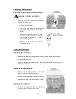
Page 18: ...by the Turfmech Machinery Limited warranty Adjusting the bottom blade WARNING PREVENT ACCIDENTS Always wear suitable safety gloves when handling the cylinder Tilt the mower backwards Hold a thin piece of paper between the edge of the bottom blade and the cutting cylinder Turn the cutting cylinder slowly If the blade is set properly the paper should cut cleanly along its full length If it does not ...

Page 19: ...gap Rotate the adjuster anti clockwise to decrease the gap Clockwise Anti clockwise Adjust the clearance between the bottom blade and the cutting cylinder so that the paper is cleanly cut at all points across the blade The cylinder should still turn without undue resistance Frequently use the paper test between each adjustment ...

Page 20: ...ken off the grub screw on the collar behind the adjuster as shown rotate the adjuster anti clockwise 1 8th of a turn Tighten the grub screw Check the adjuster it should now be easier to turn Carry out blade adjustment as described above Cylinder and bottom blade grinding reconditioning The cutting performance of the Buffalo mower is highly dependent on the condition of both the cylinder and bottom...

Page 21: ...ottom blade and the rearward end of the bar makes contact with the underside of the rear roller It is essential that the rear of the bar is under the centre of the rear roller this may require the machine to be driven onto blocks to aid access Adjust the height of the front roller until the setting bar just touches it To adjust the position of the front roller Locate the fasteners which secure the...

Page 22: ...rying out maintenance procedures it is essential that The engine is not running The parking brake is engaged The cutting cylinder is disengaged The rear roller drive is disengaged The safety precautions in this manual have been read and understood WARNING PREVENT ACCIDENTS Engine oil will be hot after machine use Allow the engine to cool before working on the machine particularly when changing oil...

Page 23: ...hat care is taken to avoid spillages Avoid contact with skin wash spillages off with soap and water Avoid contact with eyes wash with running water and seek medical attention if symptoms persist Avoid ingestion if swallowed seek medical attention IMPORTANT PREVENT ENVIRONMENTAL DAMAGE When disposing of hazardous waste products take them to an authorised disposal site Waste products must not be all...

Page 24: ...rs Chain and belt tension Inside guards Spark plug Fuel hose Front roller brgs seals Rear roller cylinder brgs Clean Debris grass from mower Engine cooling baffles Fuel sediment bowl Air filter elements Test Parking brake On off switches Drive engagement Replace Engine oil Spark plugs Air filter elements Bottom blade grind cyl Drive belts The maintenance schedule is a guide only and will vary acco...

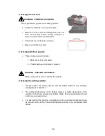
Page 25: ...as necessary see p24 Checking the air cleaner condition Locate the air cleaner on top of the engine Remove the wing nut on the top of the air cleaner and remove the outer cover Undo the wing nut which retains the filter elements Check for rips and tears in the foam element replace if damaged If necessary clean the element as described in the weekly maintenance section p22 Check the condition of th...

Page 26: ...cover Top of mower 2 Plastic belt guard LH side of mower WARNING PREVENT ACCIDENTS Always wear gloves when handling the cylinder Checking the cutting cylinder Visually inspect the cutting cylinder and the bottom blade for any damage misalignment or distortion The cutting performance of the Buffalo mowers is highly dependent on the condition of both the cylinder and bottom blade Poorly maintained p...

Page 27: ... page 25 if necessary Testing the ignition on off switches Start the engine Once the engine is running turn the on off switch on the handlebars to the OFF position the engine should stop immediately WARNING PREVENT ACCIDENTS If the engine does not stop DO NOT USE THE MACHINE contact your Turfmech Allett dealer Carry out the same procedure for the on off switch on the engine ...

Page 28: ... bowl WARNING PREVENT ACCIDENTS Wear protective gloves and safety glasses Locate the fuel sediment bowl Move the fuel cut off switch to the OFF position Place a container underneath the sediment bowl to catch any fuel and then unscrew the retaining screw at the bottom Remove the screw and sediment bowl together with the rubber gasket and retain in a safe place Wash the sediment bowl using fresh pe...

Page 29: ...ecessary see p26 To check whether the cutting cylinder drive belt is correctly tensioned you must first ensure that the engine is OFF and the parking brake is engaged Pull the cutting cylinder drive handle towards the handlebar At around 30mm from the handlebar the drive to the cylinder should begin to engage If the drive does not engage then the belt needs to be adjusted see page 25 If resistance...

Page 30: ...ge Replace the spark plug and refit the high tension lead Yearly Maintenance Replacing the spark plug Remove the spark plug as described in the 6 monthly maintenance section Fit the new spark plug Start the engine and ensure that it runs smoothly before carrying out any further maintenance Replacing air filter elements Remove the air filter elements foam and paper from their housing see p19 Fit ne...

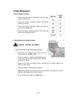
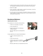
Page 31: ...pstick hole The level should be set at the top thread of the dipstick hole Miscellaneous Maintenance Adjusting cable tensions Fine adjustments can be made as described below Locate the in line adjuster on the cable Loosen the locking nut Adjust the cable tension as necessary by rotating the adjuster When the cable tension is correct tighten the lock nut Coarse adjustments can be made as described ...

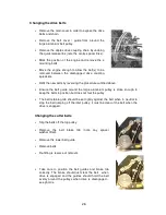
Page 32: ...e belt guide around the large aluminium pulley is close enough to keep the belts in position but does not foul the pulley The belt retaining tab should be set lightly against the belt when in neutral to stop the belt jumping off the idler pulley it must be clear of the belt when the drive is engaged Changing the cutter belts Slip the belts off the top pulley Remove the belt brake tab note any spac...

Page 33: ...hain sprocket This should be carried out by Turfmech Machinery Limited or an authorised Allett dealer Cylinder and bottom blade servicing This should be carried out by Turfmech Machinery Limited or an authorised Allett dealer see p20 ...

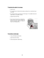
Page 34: ...orage Clean the machine so that it is clear of grass and any other debris Repair any worn or damaged parts replace with genuine Turfmech Allett parts if new parts are required Check all bolts and tighten as necessary Repair any damaged paint work Apply a wax coat to all panels standard automotive wax can be used Allow all belts to dry before storing Lubricate all grease points and apply a thin coa...

Page 35: ...the drain plug on the sediment bowl and collect the fuel in a suitable container Close the fuel shut off tap The engine should be left in compression Gently pull the recoil starter handle until you feel resistance allow the handle to return to its stowed position Removing from storage Carry out the daily inspection list Open the fuel shut off tap Check tyre pressures where fitted ...

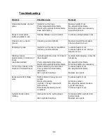
Page 36: ...ion of travel Cylinder speed too slow for forward travel speed Cylinder belts slipping adjust as necessary washboard effect Poorly adjusted bottom blade Blunt cutting cylinder bottom blade Re adjust bottom blade Grind recondition as necessary Tram lining of grass in the direction of forward travel Bottom blade in ground contact Poor cylinder to bottom blade adjustment Increase height of cut Re adj...

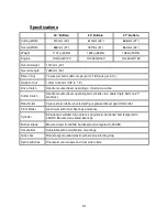
Page 37: ...ng a V belt via a cable Cutter Clutch Handle mounted lever operating twin V belts via a cable triple belts on 27 machine Rear Roller 2 piece steel rubber covered with pre greased bevel gear differential Front Roller Aluminium with roller bearings and seals Cylinder 8 bladed all welded high carbon spring steel hardened and tempered to 45HRC Mounted on sealed bearings Bottom Blade Manufactured from ...

Page 38: ...32 ...

Page 39: ...33 BUFFALO 20 24 27 PARTS SECTION ...

Page 40: ...34 ...

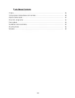
Page 41: ...Manual Contents Chassis 36 Cutting Cylinder Bottom Blade and Front Roller 38 Engine and Drive Shaft 42 Drive Train Components 44 Parking Brake 50 Handlebars and Control Cables 52 Rear Drive Roller 56 Grassbox 60 ...

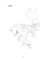
Page 42: ...36 Chassis ...

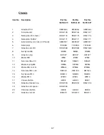
Page 43: ...0333 7 Grassbox arm RH BSG1068 BSG1068 BSG1068 8 Nut Nylock M8 NNM8 NNM8 NNM8 9 Grassbox stop AB1027 AB1027 AB1027 10 Washer M8 WM8 WM8 WM8 11 Set screw M6 x 20 SM620 SM620 SM620 12 Washer spring M6 SWM6 SWM6 SWM6 13 Washer M6 form G WM6G WM6G WM6G 14 Set screw M10 x 40 SM1040 SM1040 SM1040 15 Nut Nylock M10 NNM10 NNM10 NNM10 16 Washer M10 WM10 WM10 WM10 17 Chassis Buffalo AB001 AB020 AB021 18 Gra...

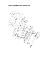
Page 44: ...38 Cutting Cylinder Bottom Blade and Front Roller ...

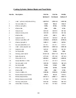
Page 45: ...S11011 S11011 S11011 12 Label cutter adjuster red AM81033 AM81033 AM81033 13 Adjuster screw AB1001 AB1001 AB1001 14 Nut Nylock M6 NNM6 NNM6 NNM6 15 Delivery plate bracket BSG1129 BSG1130 BSG1131 16 Belleville washer W11030 W11030 W11030 17 Roll pin M10 x 30 AM89341 AM89341 AM89341 18 Screw 3 8 UNF x 1 CSK S11010 S11010 S11010 19 Set screw M10 x 25 SM1025 SM1025 SM1025 20 Nut Nylock M8 NNM8 NNM8 NN...

Page 46: ...40 Cutting Cylinder Bottom Blade and Front Roller ...

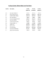
Page 47: ...B015 8 AB016 8 32 Set screw M8 x 25 SM825 SM825 SM825 33 Front roller adjuster bracket AB1072 AB1072 AB1072 34 Bracing bar Buffalo BG1026 BG1027 BG1028 35 Locking collar front roller BG003 BG003 BG003 36 Screw grub M8 x 8 ACGM8 ACGM8 ACGM8 37 Grease seal AM81513 AM81513 AM81513 38 Bearing 20mm AM81007 AM81007 AM81007 39 Front roller plain BSG1264 BSG1265 BSG1266 40 Front roller shaft Buffalo BG100...

Page 48: ...42 Engine and Drive Shaft ...

Page 49: ...8 Duplex AM89475 AM89475 AM89475 8 Cylinder drive shaft Buffalo BSG1030 BSG1031 BSG1032 9 Exhaust deflector AM81476 AM81476 AM81476 10 Screw grub M6 x 6 ACGM6 ACGM6 ACGM6 11 Locking collar AM81000 AM81000 AM81000 12 Grease nipple M6 x 45O GNM645 GNM645 GNM645 13 Bearing 20m flanged AM81008 AM81008 AM81008 14 Platewheel 16T 3 8 BSG1052 BSG1052 BSG1052 15 Screw cap head 1 2 UNF x 1 1 4 S11022 S11022...

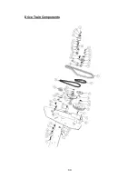
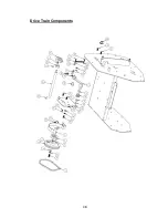
Page 50: ...44 Drive Train Components ...

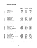
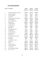
Page 51: ...y 20 shown AM92406 24 AM92406 27 AM92406 27 13 Key 1 4 x 21 AM81011 AM81011 AM81011 14 Locknut 3 4 BSF N11013 N11013 N11013 15 Sprocket rear roller 19T BG008 BG008 BG008 16 Chain 1 2 AM89436 AM89436 AM89436 17 Cutting cylinder belt 20 shown AM91451 AM91451 AM91451 18 Cutter clutch arm BSG002 BG015 BG015 19 Bearing 12mm AM82104 AM82104 AM82104 20 Pulley cutter clutch 20 shown BSG1034 BG1022 BG1022 ...

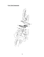
Page 52: ...46 Drive Train Components ...

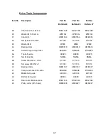
Page 53: ...9mm AM90513 AM90513 AM90513 35 Small compound sprocket BSG025 BSG025 BSG025 36 Top belt guide AB029 AB029 AB029 37 Nut Nylock M6 NNM6 NNM6 NNM6 38 Screw 3 8 UNF x 1 CSK S11010 S11010 S11010 39 Set screw 3 8 UNF x 1 S11014 S11014 S11014 40 Bearing 20mm AM81007 AM81007 AM81007 41 Compound eccentric centre BSG008 BSG008 BSG008 42 Middle belt guide AB1000 AB1000 AB1000 43 Bottom belt guard AB009 AB009...

Page 54: ...48 Drive Train Components ...

Page 55: ... Drive clutch arm BSG064 BSG064 BSG064 12 Washer M6 WM6 WM6 WM6 13 Set screw 3 8 UNF x 3 4 S11011 S11011 S11011 14 Nut Nylock M6 NNM6 NNM6 NNM6 15 Shaft retaining plate BSG003 BSG003 BSG003 16 Washer M6 Form G WM6G WM6G WM6G 17 Needle roller AM81002 AM81002 AM81002 18 Drive clutch jockey 20 shown BSG018 BSG098 BSG098 19 Bronze bush AM82654 AM82654 AM82654 20 Nut plain M6 NM6 NM6 NM6 21 Screw 3 8 U...

Page 56: ...50 Parking Brake ...

Page 57: ...SG045 BSG045 3 Nut Nylock M6 NNM6 NNM6 NNM6 4 Set screw M6 x 25 SM625 SM625 SM625 5 Set screw M6 x 20 SM620 SM620 SM620 6 Yoke anchor point BSG1024 BSG1024 BSG1024 7 Washer M6 WM6 WM6 WM6 8 Brake lever base plate BSG1089 BSG1089 BSG1089 9 Screwlock body BSG046 BSG046 BSG046 10 Washer M6 Form G WM6G WM6G WM6G 11 Cable roller drive BSG1078 BSG1078 BSG1078 ...

Page 58: ...52 Handlebars and Control Cables ...

Page 59: ...9503 AM89503 AM89503 12 Throttle lever AM82177 AM82177 AM82177 13 Throttle cable AM89500 AM89500 AM89500 14 Cable roller drive BSG1078 BSG1078 BSG1078 15 Lower anti vibration plate BSG094 BSG094 BSG094 16 Handle bar clamp BSG1020 BSG1020 BSG1020 17 Washer M8 WM8 WM8 WM8 18 Set screw 5 16 UNF x 2 1 4 B11001 B11001 B11001 19 Nut Nylock M10 NNM10 NNM10 NNM10 20 Adjuster spring anchor BSG109 BSG109 BS...

Page 60: ...54 Handlebars and Control Cables ...

Page 61: ...16 SM816 SM816 SM816 32 Spring RT 00003098 RT 00003098 RT 00003098 33 Nut plain M8 NM8 NM8 NM8 34 Nut plain M10 NM10 NM10 NM10 35 LH pivot bracket BSG110 BSG110 BSG110 36 Lower buffer BSG1236 BSG1236 BSG1236 37 Top buffer BSG1235 BSG1235 BSG1235 38 RH pivot bracket BSG111 BSG111 BSG111 39 Bottom handle BSG101 BSG102 BSG103 41 Spacer AFK1132 AFK1132 AFK1132 41 On off switch harness not shown BSG035...

Page 62: ...56 Rear Drive Roller ...

Page 63: ... BSG1045 BSG1045 BSG1045 12 Nut Nylock M6 NNM6 NNM6 NNM6 13 Set screw 3 8 UNF x 3 4 S11015 S11015 S11015 14 Washer M8 WM8 WM8 WM8 15 Washer spring M8 SWM8 SWM8 SWM8 16 Oilite bush BSG1102 BSG1102 BSG1102 17 LH pivot bracket BSG110 BSG110 BSG110 18 Bevel gear steel BSG1100 BSG1100 BSG1100 19 Bronze bush AM81143 AM81143 AM81143 20 Rear roller BG022 BG023 BG024 21 Bearing 25mm self lubricating AM8104...

Page 64: ...58 Rear Drive Roller ...

Page 65: ...on Part No Part No Part No Buffalo 20 Buffalo 24 Buffalo 27 29 Rear roller lock collar BSG016 BSG016 BSG016 30 Differential centre BSG024 BSG024 BSG024 31 Pinion gear steel BSG1101 BSG1101 BSG1101 32 Key 1 4 x 1 1 4 AM92888 AM92888 AM92888 ...

Page 66: ...60 Grassbox ...

Page 67: ...ush BSG1050 BSG1050 BSG1050 3 Grassbox plate BSG1029 BSG1029 BSG1029 4 Label Allett 15 AM81031 AM81031 AM81031 5 Grassbox Buffalo AM89511 AM89510 AM92510 6 Grassbox stiffener BSG006 BSG1021 BSG1022 7 Grassbox arm RH BSG1068 BSG1068 BSG1068 8 Grassbox arm LH BSG010 BSG010 BSG010 9 Washer M10 WM10 WM10 WM10 10 Set screw M10 x 20 SM1020 SM1020 SM1020 ...

Page 68: ...62 Notes ...
Reviews: