background image

F016J13542-A ISSUE 28-01-22 SE 


16 

Power indicator LED (15) 

 
The mower is equipped with a power indicator to indicate the charge status of the battery pack and the working 
status of the mower. The power indicator will illuminate when the cylinder/reel is rotating. Below is a description 
of possible status meanings: 


Power Indicator on Mower 

Meaning 

Action 

Shining green 

Mower is working properly 

N/A 
 

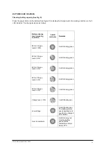
Flashing green 

Handle is in storage/maintenance 
position or cartridge securing lever is 
not in the proper position 

Check quick-adjust Lever and move 
the cartridge lever to the fully locked 
position 

Flashing red  

The battery is depleted  

Stop the mower and charge the 
battery pack 

Solid orange 

The mower is overheated 

Remove the battery from the mower, 
move them to the shade and cool for 
at least 15 minutes 

Flashing orange 

The mower is overloaded 

Slow down your pace or raise up the 
cut height to decrease the load 

Red and green flashing 
alternately 

Communication timeout 

Contact Allett 


Starting and stopping (See Fig. F 

– I) 

 
The blade continues to rotate for a few seconds after the machine is switched off. Allow the motor/blade to stop 
rotating before switching “on” again. To aid starting when using a cultivation cartridge push the handle (1) down 
lift the front wheels/roller from the floor.  


The cutting blades and self-propel function are independent of each other and may be operated individually. For 
example, it is good practice when transporting the mower to have the blades turned off. 
 
NOTICE: The cutting blades cannot be started unless: 
The handle is locked into one of the three operating positions, see 

“handle height adjustment”. 

The cartridge securing lever is fully forward and retaining the cartridge securely 
 
NOTICE: To prevent serious injury, we recommend that you start the mower with self-propelled function off. 


To Start the cutting blades

 (Fig. F)  

 
Make sure there is a battery in the battery dock (2) and the isolation key (16) is in the key slot. 
 

1.  Depress the safety button (12) down. 


2.  With the safety button (12) depressed, pull the bail switch (11) upward to meet the handle and release 

the safety button. 


To Stop


the cutting blades

 (See Fig. H) 

 
Fully release the bail switch, the electric brake in the Automatic Braking Mechanism will stop the blade rotation 
within 3 seconds of the bail switch release. 
 
It is good practice to turn the 

RotoShift™ grip off until it can’t be rotated. 


To Start the self-propel function

 (See Fig. G) 


1.  Press one of the self-propel switches (13). 


2.  Turn the RotoShift

™ grip (10) until you hear a “click”.


Summary of Contents for STIR43

Page 1: ...IR51 1 OPERATOR S MANUAL For serial numbers STIR43 1 21 0001 STIR51 1 21 0001 onward Original instructions English version Allett Limited Regal House Airfield Industrial Estate Hixon Stafford ST18 0PF United Kingdom Tel 44 0 1889 271503 sales allett co uk www allett co uk For Allett spare parts tel 44 0 1889 27209 ...

Page 2: ...F016J13542 A ISSUE 28 01 22 SE 2 READ THIS MANUAL BEFORE USING AN ALLETT STIRLING 43 OR 51 CYLINDER MOWER YOUR SAFETY IS INVOLVED IT IS ESSENTIAL THAT OPERATORS STUDY THIS DOCUMENT FOR THEIR OWN SAFETY ...

Page 3: ...ller 7 Cartridge securing lever 8 Quick adjust lever handle pivot 9 Handle locking clamp 10 RotoShift grip 11 Cylinder bail bar 12 Safety button 13 RotoShift switch 14 Battery release button 15 Power indicator 16 Isolation key EGO CH2100E Standard Charger EGO CH5500E Rapid Charger EGO BA2800T 5 0Ah Battery EGO BA5600T 10 0Ah Battery ...

Page 4: ...F016J13542 A ISSUE 28 01 22 SE 4 x4 A ...

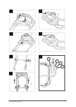
Page 5: ...F016J13542 A ISSUE 28 01 22 SE 5 2 3 1 B C A E D A ...

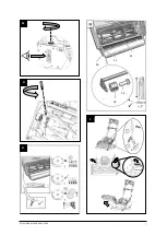
Page 6: ...F016J13542 A ISSUE 28 01 22 SE 6 K1 K2 K3 K4 F A G A H I J K L ...

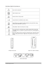
Page 7: ...F016J13542 A ISSUE 28 01 22 SE 7 M O P Q 22 21 20 18 18 19 1 2 ...

Page 8: ...paired only by persons who are familiar with its characteristics and who are familiar with the relevant safety procedures The safety precautions outlined in this manual and all other generally recognised regulations on safety must be observed at all times Any modifications carried out to a Stirling mower will relieve Allett Limited of liability for any resulting damage or injury Allett Limited res...

Page 9: ... unattended for any period Sharp blade s Beware of severing toes or fingers Wait until all machine components have completely stopped before touching them The blades continue to rotate after the machine is switched off a rotating blade can cause injury Never allow children to use the lawnmower children should be supervised to ensure they do not play with the machine Always remove the isolation key...

Page 10: ... Exercise extreme caution when changing direction on slopes Do not mow excessively steep slopes Use extreme caution when stepping back or pulling the lawnmower towards you Never mow by pulling the mower towards you Stop the blades if the lawnmower has to be tilted for transportation when crossing surfaces other than grass and when transporting the lawnmower to and from the area to be mowed Do not ...

Page 11: ...eplace worn or damaged parts for safety Ensure replacement parts fitted are approved TECHNICAL DATA Designation Stirling 43 battery Cylinder lawnmower Stirling 51 battery Cylinder lawnmower Machine Model type STIR43 1 STIR51 1 Voltage Max V 56V DC 56V DC Blade width cm 43 51 Height of cut mm 10 50 10 50 Grass box capacity l 62l 70l Self propelled Weight kg 53kg 57kg IP rating IPX4 IPX4 DELIVERED I...

Page 12: ...ce position the handle on the mower pass the handle through the slots so it rests in the mounting blocks Tuck any spare cable in the tray below the mounting blocks 3 Pivot the handlebars up and lock in the upright storage maintenance position using the quick adjust lever see section on Handle height adjustment 4 Fit the cover plate to secure the handle to the mower Use 4 x M6 x 50mm fasteners 4 x ...

Page 13: ...el working condition 5 LED indicator Remarks 80 Charge level 100 5 LED shining green 60 Charge level 80 4 LED shining green 40 Charge level 60 3 LED shining green 20 Charge level 40 2 LED shining green 10 Charge level 20 1 LED shining green Charge level 10 1 LED flashing red Low voltage 5 LED flashing red The battery pack is nearly depleted and needs to be charged immediately Over temperature 5 LE...

Page 14: ...en using the lawnmower always remove the isolating key 16 when leaving the lawnmower unattended and never let children play with the machine Following this rule will reduce the risk of electric shock fire or serious injuries Inserting and removing the battery from the mower See Fig E WARNING If any parts are broken or missing do not attempt to attach the battery pack to the mower or operate the mo...

Page 15: ...damaged or modified Damaged or modified batteries may exhibit unpredictable behaviour resulting in fire explosion or risk of injury Do not expose a battery pack or tool to fire or excessive temperature Exposure to fire of temperature above 130 C may cause explosion Protective circuit The battery includes a protection circuit that will immediately turn off the battery should its temperature exceed ...

Page 16: ...ng on again To aid starting when using a cultivation cartridge push the handle 1 down lift the front wheels roller from the floor The cutting blades and self propel function are independent of each other and may be operated individually For example it is good practice when transporting the mower to have the blades turned off NOTICE The cutting blades cannot be started unless The handle is locked i...

Page 17: ... 50 mm for mowing grass for sports surfaces a lower height of cut is achievable with the 10 blade cartridge and sports blade option Your mower can use cultivation cartridges purchased separately to a maximum depth of 15mm below the surface The height of cut is adjusted by turning the knob 7 at the right hand side of the machine The comb will also require adjustment see Comb Adjustment The numbered...

Page 18: ...ing minimal contact between the cylinder reel and bottom blade bed knife is critical to help reducing noise emissions see Adjusting the blade section Damaged belts or loose guards can increase noise emissions Therefore periodically inspect the mower for signs of wear and ensure the guards are securely attached and in good condition Changing a UC lawn care cartridge See Fig P The mower is fitted wi...

Page 19: ...e lawnmower they may be cleaned with water from a hose Lubricate the cutting cylinder reel with a light oil to displace any water after cleaning and when storing at the end of the season Remove the battery and isolation key store both machine battery and charger in a safe cool and dry place avoiding areas of high humidity At the end of the season do not store the battery in the mower Keep it in sh...

Page 20: ...F016J13542 A ISSUE 28 01 22 SE 20 DRIVE BELT ROUTING DIAGRAM ITEM NO PART NUMBER DESCRIPTION QTY 1 F016J13298 CARTRIDGE DRIVE BELT 1 2 F016J13342 REAR ROLLER DRIVE BELT 1 1 2 ...

Page 21: ...nife Check the cylinder reel is set correctly and not too tight against the bottom blade bed knife Cartridge securing lever in open safe position Check cartridge securing lever is fully forward 7 UC cartridge does not start Mowing or working too low for start up When engaging blades tilt the mower back slightly so the blades are just clear of the ground before lowering slowly Cartridge securing le...

Page 22: ... BS EN ISO 5395 Measured Sound power level 2000 14 EC Guaranteed sound power level 2000 14 EC Stirling 43 43cm 71 dB LPA 81 dB LWA 86 dB LWA Stirling 51 51cm 71 dB LPA 87 dB LWA 90 dB LWA Vibration emission values triaxial vector sum determined according to BS EN 60335 2 77 Model number Vibration Uncertainty K Stirling 43 43cm 1 7 m s2 0 3 m s2 Stirling 51 51cm 1 7 m s2 0 3 m s2 Notified body Vinc...

Page 23: ...fe is dependent on regular servicing and they are not therefore normally covered by the guarantee Examples of wearing parts are as follows cutting cylinder bottom blade cylinder roller drive belts cables bearings chains sprockets plastic drive gears pulleys any friction related parts and other parts what have contact with the ground Any of the above parts replaced without prior authorisation will ...

Reviews: