background image

Linear Programmable Power Supply

AF2303P

  User Manual 

AF

  SERIES PRODUCT OF ALLFTEK 

Summary of Contents for AF Series

Page 1: ...Linear Programmable Power Supply AF2303P User Manual AF SERIES PRODUCT OF ALLFTEK ...

Page 2: ......

Page 3: ...UND THE INSTRUMENT This product is provided with a protective earth terminal To minimize shock hazard the instrument chassis and cabinet must be grounded The instrument must be connected to the AC power supply mains through a three conductor power cable with the third wire firmly connected to an electrical ground safety ground at the power outlet For instruments designed to be hard wired to the AC...

Page 4: ...ce components with power cable connected Under certain conditions dangerous voltages may exist even with power cable removed To avoid injuries always disconnect power discharge circuits and remove external voltage sources before touching components DO NOT SERVICE OR ADJUST ALONE Do not attempt internal service or adjustment unless another person capable of rendering first aid and resus citation is...

Page 5: ...SONNEL WARNING The WARNING sign denotes a hazard It calls attention to a procedure practice or the like which if not correctly performed or adhered to could result in personal injury Do not proceed beyond a WARNING sign until the indicated conditions are fully understood and met CAUTION The CAUTION sign denotes a hazard It calls attention to a procedure practice or the like which if not correctly ...

Page 6: ...e power supply is isolated from earth ground Either output terminal may be grounded or the output may floated up to 240 Vdc including output voltage from chassis ground 1 6 Specifications TRIPLE OUTPUT LINEAR POWER SUPPLY UP TO 165 WATTS Model MAX OUTPUT POWER AF2303P 165 WATTS OUTPUT VOLTAGE Output Voltage 0 to 30V 0 to 30V Fixed 3 3V 5V Setting Resolution 10mV Max output voltage 32V 32V Dual tra...

Page 7: ...NSTANT VOLTAGE CHARACTERISTICS at rated output 2 5A Line regulation for change of AC 10 5mV 5mV Load regulation for load change 0 100 10mV 10mV Ripple Noise rms 1 5mVrms 2mVrms Ripple Noise p p 20mVp p 20mVp p Transient Response 200ps Typical Temperature Coefficient 100ppm C Typical CONSTANT CURRENT CHARACTERISTICS at rated output 2 5A Line regulation for change of AC 10 15mA Typical Load regulati...

Page 8: ...AC 115V 2 5AT 250V for AC 230V Options RS 232 Accessories User s manual power cord fuse For output less than 5 of rated output add 5 digits to the accuracy specification RS232 Interface capabilities 1 RS232C DCE interface 9 pin D SUB connector 2 Port configuration asynchronous 2400 baud 8 data bits 1 stop bits no parity 2 INSTALLATION 2 1 Introduction This section contains instructions for checkin...

Page 9: ...ed it must be installed in a location that allows sufficient air flow Allow 1 inch 25mm of space on all four sides of the power supply 2 4 Input power requirements You can operate this power supply from a nominal 115V or 230 240 Vac single phase power source at 47 to 63Hz You can check the line voltage setting of your supply of your supply by examining the label on the rear panel 2 5 Line fuse The...

Page 10: ...FIGURE A GETTING STARTED ...

Page 11: ... the voltage settings when the supply is in the CV mode or the current settings when the supply is in the CC mode by 10mV or 1mA per step If the key is pressed and held it will continually decrease the setting until it is released 7 Vset 4 output control key used to display or alter the present voltage number 4 8 Iset 5 output control key used to display or alter the present voltage number 5 9 up ...

Page 12: ...nal BLACK The common terminal which is used for 30V 2 5A output 21 output Terminal YELLOW This terminal is used to output 30V 2 5A with respect to the COM1 terminal 22 GND Terminal GREEN This ground earth terminal is connected to the main chassis 23 COM2 Terminal BLACK The common terminal which is used for 5V 3A or 3 3V 3A output 24 5V 3 3V Terminal RED This terminal is used to output 5V 3A or 3 3...

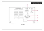
Page 13: ...ine fuse 3 RS 232C interface 9 pin female DCE interface 4 Electrical Rating Label Indicator of input power requirements and fuse rating 5 Voltage Swtich Selector 115Vac or 230Vac 10 10 50 60Hz Position 1 Indicator of CV mode or CC mode of output positive It will flash when the output is enabled Position 2 Indicator of CV mode or CC mode of output negative It will flash when the output is enabled P...

Page 14: ...FIGURE C GETTING STARTED ...

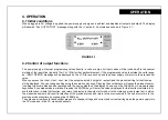
Page 15: ...selected output or output and the present setting for that function will be displayed You can change setting using the numeric entry keys Pressing the number keys will cause the present numer ic setting to become blank and be replaced with the new numbers on the display You can use the CLEAR key to erase previous keystrokes if you made make a mistake Pressing the ENTER key will enter the values di...

Page 16: ...ut channel can be turned on and off from the front panel The output on off key toggles both the output and output on and off simultaneously The key toggles the 5V or 3 3V output on and off An output disabled by the output on off key will be have as if it were programmed to zero volts 4 4 Overload protection for of 5V or 3 3V output When the 5V or 3 3V output current is approximately 20 percent abo...

Page 17: ...appear on the LCD Step 3 Repeat step 2 Key in the measured value i e if the DMM shows 29 798V then key in 29 798 followed by the ENTER key The following message will then appear on the LCD Step 4 Measure the DC current from out terminals and COM1 with the DMM and key in the value i e if the DMM shows 0 728A then key in 0 728 followed by the ENTER key The following message will then appear on the L...

Page 18: ... DC voltage from output terminals and COM1 with the DMM and key in the measured value i e if the DMM shows 9 624V then keyin 9 624 followed by the ENTER key The following message will then appear on the LCD Step 7 Repeat step 6 Keyin the measured value i e if the DMM shows 30 036V then key in 30 036 followed by the ENTER key The following message will then appear on the LCD CALIBRATION ...

Page 19: ... i e if the DMM shows 0 642A then key in 0 642 followed by the ENTER key The following message will then appear on the LCD Step 9 Repeat step 8 Key in the measured value i e if the DMM shows 2 418A then key in 2 418 followed by the ENTER key The following message will then appear on the LCD CALIBRATION ...

Page 20: ...ce it with a replacement fuse as specified in the label on the rear panel 4 Replace the fuse in the fuse holder and re install 5 Reconnect the AC power cord NOTE USE OF ANY FUSE OTHER THAN THE ONE SPECIFIED MAY CAUSE DAMAGE TO THE UNIT POSE A SEVERE FIRE HAZARD AND WILL VOID THE WARRANTY 6 2 In Case of Difficulties This programmable power supply has been designed to be accurate reliable and easy t...

Page 21: ...ction describes how hoe to set up the RS 232 C interface for remote control The interface of LPS305 are designed in accordance with EIA Electronic Industries Association standard RS 232 C Through its interface be LPS305TPT 3025 be remotely controlled and transmit its internal data to a hose computer Command Description Example VSET1 CH1 Voltage setup VSET1 5 VSET2 CH2 Voltage setup VSET2 10 ISET1 ...

Page 22: ... return 5 There is only one command allowed in a command string 6 A command string enters before OK prompt will be reject no function 7 STATUS Command operation explanation The power supply responses the STATUS command with a 10 bit binary number Each bit representing the information as below Bit 0 channel 1 0 CV 1 CC Bit 5 0 digital output 5V 1 digital output 3 3V Bit 9 0 beeper function off 1 be...

Page 23: ......

Page 24: ...Made in allftek AFYS 14 305 1 ...

Reviews: