background image

www.comlaundry.com

Part No. 800383R2

February 2003

Ser

v

ice

Commercial

Frontload

Washers

Refer to Page 3 for Model Numbers

H018C

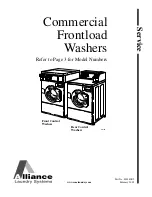
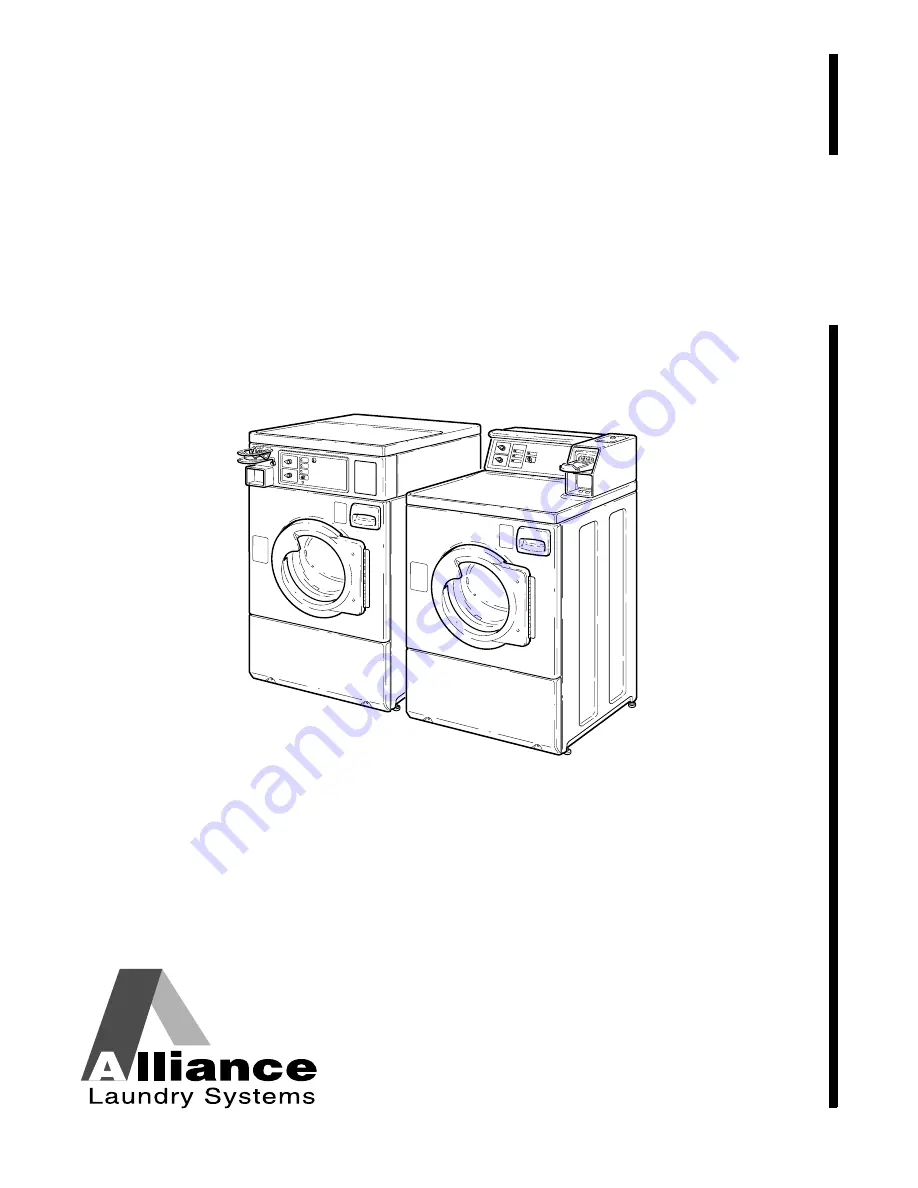
Front Control
Washers

Rear Control
Washers

Summary of Contents for 261*H

Page 1: ...www comlaundry com Part No 800383R2 February 2003 Service Commercial Frontload Washers Refer to Page 3 for Model Numbers H018C Front Control Washers Rear Control Washers...

Page 2: ...17 Washer Will Not Start No Door Lock 44 18 Washer Will Not Start Control Analysis 46 19 Washer Will Not Fill 48 20 Washer Overflows 50 21 Pump Does Not Operate 52 22 Door Locked Motor Does Not Run E...

Page 3: ...61 E SWR261 E HWF261 H HWR261 H SWF261 H and SWR261 H Through Serial Number 0007013011 138 Models HWF261 H HWR261 H SWF261 H and SWF261 H Starting Serial Number 0007013012 139 Models HWRB61 J1102 SWRB...

Page 4: ...ese washers Model Number Front Control Rear Control HWF261 E X HWF261 H X SWF261 E X SWF261 H X HWR261 E X HWR261 H X HWRB61 J1102 X HWRY61 H1102 X HWRZ61 H X HWRZ61 H1102 X SWR261 E X SWR261 H X SWRB...

Page 5: ...NOTE are followed by specific instructions IMPORTANT The word IMPORTANT is used to inform the reader of specific procedures where minor machine damage will occur if the procedure is not followed NOTE...

Page 6: ...expires Alliance Laundry Systems also recommends contacting an authorized technician and using authorized factory parts To reduce the risk of electric shock fire explosion serious injury or death Disc...

Page 7: ...m the machine was purchased or contact Alliance Laundry Systems at 920 748 3950 for the name and address of the nearest authorized parts distributor For technical assistance call 920 748 3121 Nameplat...

Page 8: ...ECTRIC DRAIN PUMP MOTOR OUTER TUB INNER BASKET MIXING VALVE PRESSURE SWITCH Located inside control cabinet TIMER Located inside control cabinet H197SE3A TEMPERATURE SWITCH SPEED SWITCH START SWITCH EL...

Page 9: ...into the inner basket via the mixing valve until the pressure switch shuts off the water while agitating The rinse cycle consists of agitation for a predetermined amount of time then a spin mode with...

Page 10: ...T COPY or TRANSMIT How Your Washer Works Electronic Control Models FLW1650S MOTOR CONTROL BOARD Located inside control hood PRESSURE SWITCH Located inside control hood ELECTRONIC CONTROL Located insid...

Page 11: ...nse cycles have been completed the washer goes into a final high spin cycle to extract as much water as possible from the clothing to prepare them for the dryer The spin speeds and duration of this fi...

Page 12: ...switch The wiring diagram may show the out of balance switch as a normally open switch which is incorrect The switch is a normally closed switch b To test the electrical circuit disconnect electrical...

Page 13: ...with any guards panels removed Whenever ground wires are removed during servicing these ground wires must be reconnected to ensure that the washer is properly grounded W003 WARNING Copyright Alliance...

Page 14: ...service the motor brushes NOTE Verify that motor is receiving proper voltage Disconnect electrical power to washer Test Procedure a At the rear of the washer remove the lower access panel b Reach in t...

Page 15: ...Using a flashlight view brushes through holes in motor end shield Refer to Figure 2 c Inspect both brushes to determine if either brush braided wire is binding the brush movement The braided wire mig...

Page 16: ...LLC DO NOT COPY or TRANSMIT d After determining which brush assembly is binding carefully use the tip of a small screwdriver to unsnag and reposition the braided wire Refer to Figure 3 Make sure sprin...

Page 17: ...econnected to ensure that the washer is properly grounded W003 WARNING Copyright Alliance Laundry Systems LLC DO NOT COPY or TRANSMIT Service Procedure Worn Brushes a Remove motor from washer Refer to...

Page 18: ...ound wires are removed during servicing these ground wires must be reconnected to ensure that the washer is properly grounded W003 WARNING Copyright Alliance Laundry Systems LLC DO NOT COPY or TRANSMI...

Page 19: ...before servicing Never start the washer with any guards panels removed Whenever ground wires are removed during servicing these ground wires must be reconnected to ensure that the washer is properly...

Page 20: ...er contact MA completes circuit to control relay CR1 row 1 normally closed contacts With door open or either door switch bad CR1 is de energized turning on Close Door Light 3 Timer contact MA complete...

Page 21: ...800383 23 Section 3 Troubleshooting Electromechanical Models Copyright Alliance Laundry Systems LLC DO NOT COPY or TRANSMIT H251SE3A POWER NEUTRAL VEND SATISFIED DOOR CLOSED 1 2 3 4 5 4 5 6...

Page 22: ...washer is properly grounded W003 WARNING Copyright Alliance Laundry Systems LLC DO NOT COPY or TRANSMIT 4 START AND DOOR LOCK 1 Timer contact MA is closed by mechanical actuation coin slide or timer a...

Page 23: ...800383 25 Section 3 Troubleshooting Electromechanical Models Copyright Alliance Laundry Systems LLC DO NOT COPY or TRANSMIT H252SE3A POWER NEUTRAL START AND DOOR LOCK 1 2 2 3 3 4 5...

Page 24: ...stems LLC DO NOT COPY or TRANSMIT 5 FILL SEQUENCE NOTE Refer to Figures 1 and 2 on pages 25 or 26 to determine which fill valves will operate Once water level is achieved full level is satisfied and L...

Page 25: ...800383 27 Section 3 Troubleshooting Electromechanical Models Copyright Alliance Laundry Systems LLC DO NOT COPY or TRANSMIT H248SE3A POWER NEUTRAL FILL 1 2 3...

Page 26: ...ry Systems LLC DO NOT COPY or TRANSMIT 6 20 VOLT CONTROL 1 During Start Up Vend Satisfied Door Closed timer contact MA is closed and 120 Volts AC is sent to auto transformer 2 Transformer supplies 20...

Page 27: ...800383 29 Section 3 Troubleshooting Electromechanical Models Copyright Alliance Laundry Systems LLC DO NOT COPY or TRANSMIT H249SE3A POWER 20 VOLT NEUTRAL 120 VOLT 20 VOLT CONTROL 1 2 5 2 4 3...

Page 28: ...re that the washer is properly grounded W003 WARNING Copyright Alliance Laundry Systems LLC DO NOT COPY or TRANSMIT 7 240 VOLT MOTOR POWER 1 During Start Up Vend Satisfied Door Closed timer contact MA...

Page 29: ...800383 31 Section 3 Troubleshooting Electromechanical Models Copyright Alliance Laundry Systems LLC DO NOT COPY or TRANSMIT H245SE3A POWER 240 VOLT NEUTRAL 120 VOLT 240 VOLT 1 4 2 3...

Page 30: ...32 800383 Section 3 Troubleshooting Electromechanical Models Copyright Alliance Laundry Systems LLC DO NOT COPY or TRANSMIT 8 TIMER CHART H223SE3A...

Page 31: ...IT 9 CYCLE TIMER MOTOR CONTROL INPUTS TIMER CONTACTS FUNCTION NOTE MA MB MC MD ME 0 0 0 0 0 Off X 0 0 0 0 Normal agitate 49 51 rpm 10 sec for 9 sec pause 20 sec rev 9 sec pause X X 0 0 0 Distribution...

Page 32: ...t Bleach Valve X 0 0 0 X X 0 0 X 0 X Fill Cold Temp Water and Detergent Bleach Valve X 0 0 0 0 X 0 0 0 X X Fill Rinse Temp Water and Softener Valve X 0 0 0 0 X 0 0 X X 0 Fill Rinse Temp Water Detergen...

Page 33: ...Copyright Alliance Laundry Systems LLC DO NOT COPY or TRANSMIT 11 WASHER DC MOTOR FUNCTIONS Agitate For agitate the DC current will flow through the full field D1 D2 of motor The washer agitation is...

Page 34: ...ensure that the washer is properly grounded W003 WARNING Copyright Alliance Laundry Systems LLC DO NOT COPY or TRANSMIT Spin For spin 0 650 rpm the DC current will flow through the full field D1 D2 of...

Page 35: ...panels removed Whenever ground wires are removed during servicing these ground wires must be reconnected to ensure that the washer is properly grounded W003 WARNING Copyright Alliance Laundry Systems...

Page 36: ...condition b If hole dimensions vary from Figure 11 replace with 685593 coin slide extension c Retest machine for proper operation with new extension INOPERATIVE CONDITION SERVICE CORRECTION Triac in...

Page 37: ...sher before servicing Never start the washer with any guards panels removed Whenever ground wires are removed during servicing these ground wires must be reconnected to ensure that the washer is prope...

Page 38: ...try again No Yes Does the Microwand prompt Control Mismatch error Is there any control response Yes Check the following Microwand battery voltage Blockage of IR window on control Attachment of IR cup...

Page 39: ...onnector properly seated on the control board No Properly reseat connection and conduct diagnostic test again Yes From the coin drop is the 3 pin connector properly plugged in Yes No Properly reseat c...

Page 40: ...ord plugged in Plug unit into an outlet and check for proper supply voltage No Yes 1 No Is there 24 Volt AC at the output side of the transformer Is there 120 AC to the primary of the transformer No N...

Page 41: ...9 COMM SD SW CV SW CD1 SVDC CD1 CD1 COMM CD2 SVDC CD2 CD2 COMM PE COMM COMM SVDC 24VDC CRP NBP SVDC COMM COMM NRFA NAG VUR RXD TXD 24VDC SVDC 1 3 5 8 4 1 7 3 6 9 2 K1 K2 H2 VCC SOMI CLK SIMO GND 3 VU...

Page 42: ...Is there 120 Volt AC across H4 4 to H6 5 on the control board 4 Replace the Door Lock Assembly No Is there 120 Volt AC across H6 1 and H6 5 on the control board No 5 Replace the Control Board No Is th...

Page 43: ...9 COMM SD SW CV SW CD1 SVDC CD1 CD1 COMM CD2 SVDC CD2 CD2 COMM PE COMM COMM SVDC 24VDC CRP NBP SVDC COMM COMM NRFA NAG VUR RXD TXD 24VDC SVDC 1 3 5 8 4 1 7 3 6 9 2 K1 K2 H2 VCC SOMI CLK SIMO GND 3 VU...

Page 44: ...Laundry Systems LLC DO NOT COPY or TRANSMIT 18 WASHER WILL NOT START CONTROL ANALYSIS Washer Will Not Start Control Analysis Is there 120 Volt AC across H6 6 to H6 5 on the control board 1 Yes No Refe...

Page 45: ...800383 47 Section 3 Troubleshooting NetMaster Models Copyright Alliance Laundry Systems LLC DO NOT COPY or TRANSMIT WASHER WILL NOT START CONTROL ANALYSIS...

Page 46: ...trol board Correct wiring between pressure switch and control board No Is there 120 Volt AC from the input side of the mixing valves to FS2 on the motor control board Yes 1 2 3 Yes Check for cracked o...

Page 47: ...MM SD SW CV SW CD1 SVDC CD1 CD1 COMM CD2 SVDC CD2 CD2 COMM PE COMM COMM SVDC 24VDC CRP NBP SVDC COMM COMM NRFA NAG VUR RXD TXD 24VDC SVDC 1 3 5 8 4 1 7 3 6 9 2 K1 K2 H2 VCC SOMI CLK SIMO GND 3 VUR NET...

Page 48: ...Washer Overflows Is there voltage to the over level terminal on pressure switch to FS2 Yes No Replace inoperative pressure switch Is there voltage across the coil of either the hot or cold water sole...

Page 49: ...M SD SW CV SW CD1 SVDC CD1 CD1 COMM CD2 SVDC CD2 CD2 COMM PE COMM COMM SVDC 24VDC CRP NBP SVDC COMM COMM NRFA NAG VUR RXD TXD 24VDC SVDC 1 3 5 8 4 1 7 3 6 9 2 K1 K2 H2 VCC SOMI CLK SIMO GND 3 VUR NETM...

Page 50: ...Not Operate Is there voltage across the wht blk and the white wire going to the motor Is there voltage across terminals H6 2 and H6 5 NOTE Check at beginning of spin drain portion of cycle If the pum...

Page 51: ...COMM SD SW CV SW CD1 SVDC CD1 CD1 COMM CD2 SVDC CD2 CD2 COMM PE COMM COMM SVDC 24VDC CRP NBP SVDC COMM COMM NRFA NAG VUR RXD TXD 24VDC SVDC 1 3 5 8 4 1 7 3 6 9 2 K1 K2 H2 VCC SOMI CLK SIMO GND 3 VUR N...

Page 52: ...ormer Using an Ohmmeter check red black wire from transformer to H1 7 on motor control board for broken wire poor connection If none found replace transformer 2 Is there continuity Check continuity at...

Page 53: ...1 2 1 8 9 COMM SD SW CV SW CD1 SVDC CD1 CD1 COMM CD2 SVDC CD2 CD2 COMM PE COMM COMM SVDC 24VDC CRP NBP SVDC COMM COMM NRFA NAG VUR RXD TXD 24VDC SVDC 1 3 5 8 4 1 7 3 6 9 2 K1 K2 H2 VCC SOMI CLK SIMO G...

Page 54: ...l try to reset the motor control by powering it down It will try resetting three times before setting the error code Common causes include defective or unplugged transformer and incorrect wiring to mo...

Page 55: ...ANSMIT 24 COINS IGNORED WHEN ENTERED Coins Ignored When Entered Start Coin Drop Diagnostic Test Refer to programming manual Reset control to ready mode Yes No Is H7 connector properly seated on the co...

Page 56: ...or TRANSMIT 25 NO VISIBLE DISPLAY ON CONTROL Control Has No Visible Display The electronic control has no LED or VFD functioning on the control board Is the power cord plugged in Plug unit into an ou...

Page 57: ...800383 61 Section 3 Troubleshooting MDC Models Copyright Alliance Laundry Systems LLC DO NOT COPY or TRANSMIT NO VISIBLE DISPLAY ON CONTROL 801182 1 2 3...

Page 58: ...NOT START NO DOOR LOCK Washer Will Not Start No Door Lock Washer will not start Vend satisfied Is there 120 Volt AC across H4 5 and H6 5 on the control board 1 2 Yes Yes Is there 120 Volt AC across H4...

Page 59: ...800383 63 Section 3 Troubleshooting MDC Models Copyright Alliance Laundry Systems LLC DO NOT COPY or TRANSMIT WASHER WILL NOT START NO DOOR LOCK 801182 5 2 3 1 4...

Page 60: ...never ground wires are removed during servicing these ground wires must be reconnected to ensure that the washer is properly grounded W003 WARNING Copyright Alliance Laundry Systems LLC DO NOT COPY or...

Page 61: ...800383 65 Section 3 Troubleshooting MDC Models Copyright Alliance Laundry Systems LLC DO NOT COPY or TRANSMIT WASHER WILL NOT START CONTROL ANALYSIS 801182 1...

Page 62: ...undry Systems LLC DO NOT COPY or TRANSMIT 28 WASHER WILL NOT FILL Is there 120 Volt AC across the input side of the pressure switch to FS2 on the motor control board Correct wiring between pressure sw...

Page 63: ...800383 67 Section 3 Troubleshooting MDC Models Copyright Alliance Laundry Systems LLC DO NOT COPY or TRANSMIT WASHER WILL NOT FILL 801182 1 3 2...

Page 64: ...res must be reconnected to ensure that the washer is properly grounded W003 WARNING Copyright Alliance Laundry Systems LLC DO NOT COPY or TRANSMIT 29 WASHER OVERFLOWS Washer Overflows Is there voltage...

Page 65: ...800383 69 Section 3 Troubleshooting MDC Models Copyright Alliance Laundry Systems LLC DO NOT COPY or TRANSMIT WASHER OVERFLOWS 801182 1 2...

Page 66: ...onnected to ensure that the washer is properly grounded W003 WARNING Copyright Alliance Laundry Systems LLC DO NOT COPY or TRANSMIT 30 PUMP DOES NOT OPERATE Pump Does Not Operate Is there voltage acro...

Page 67: ...800383 71 Section 3 Troubleshooting MDC Models Copyright Alliance Laundry Systems LLC DO NOT COPY or TRANSMIT PUMP DOES NOT OPERATE 801182 2 1...

Page 68: ...er Using an Ohmmeter check red black wire from transformer to H1 7 on motor control board for broken wire poor connection If none found replace transformer 2 Is there continuity Check continuity at te...

Page 69: ...800383 73 Section 3 Troubleshooting MDC Models Copyright Alliance Laundry Systems LLC DO NOT COPY or TRANSMIT DOOR LOCKED MOTOR DOES NOT RUN E DF ON DISPLAY 801182 2 1 4 3...

Page 70: ...d to ensure that the washer is properly grounded W003 WARNING Copyright Alliance Laundry Systems LLC DO NOT COPY or TRANSMIT Section 4 Grounding 32 WALL RECEPTACLE POLARITY CHECK Refer to Figure 12 Fi...

Page 71: ...properly grounded W003 WARNING Copyright Alliance Laundry Systems LLC DO NOT COPY or TRANSMIT 33 MACHINE GROUND CONNECTIONS FRONT CONTROL WASHERS ELECTROMECHANICAL MODELS Refer to Figure 13 1 Ground...

Page 72: ...800383 77 Section 4 Grounding Copyright Alliance Laundry Systems LLC DO NOT COPY or TRANSMIT Front Control Washers Electromechanical Models Figure 13 H009GE3A 4 5 1 2 3 6 7 8 9 10 11...

Page 73: ...ted to ensure that the washer is properly grounded W003 WARNING Copyright Alliance Laundry Systems LLC DO NOT COPY or TRANSMIT 34 MACHINE GROUND CONNECTIONS REAR CONTROL WASHERS Refer to Figure 14 1 G...

Page 74: ...800383 79 Section 4 Grounding Copyright Alliance Laundry Systems LLC DO NOT COPY or TRANSMIT Rear Control Washers Figure 14 FLW665G 1 2 3 4 5 6 7 8 9 10...

Page 75: ...s far as wires permit Refer to Figure 15 Step 3 Rear Control Washers 1 Remove two control panel attaching screws holding control panel to control hood Refer to Figure 16 Lay assembly forward on protec...

Page 76: ...available touch washer while it is plugged in before handling control to dissipate any charge a Remove two control panel attaching screws Refer to Figure 16 Lay assembly forward on protective pad on...

Page 77: ...pplied in a special anti static wrapping and protected by anti static foam While holding control by its metal edges remove control from foam and wrapping 1 Remove two control panel attaching screws Re...

Page 78: ...COPY or TRANSMIT Figure 18 H070PE3A MOTOR SPEED SWITCH PUSH TO START SWITCH NUT LOCKWASHER LOCKWASHERS INDICATOR LIGHT INDICATOR LIGHTS TEMPERATURE SWITCH CONTROL KNOB ASSEMBLY SETSCREW NUT CONTROL P...

Page 79: ...D REAR PANEL RELAYS PRESSURE SWITCH MOTOR CONTROL BOARD LOCKWASHER CAP SCREW START SWITCH NUT NUT LOCKWASHER LOCKWASHER LOCKWASHER LOCKWASHER SCREW SCREW INDICATOR LIGHTS MOTOR SPEED SWITCH TEMPERATUR...

Page 80: ...DO NOT COPY or TRANSMIT Figure 20 H117P ELECTRONIC CONTROL SCREW CONTROL SHIELD SEALING WASHER SCREW SCREW SCREW SCREW CONTROL PANEL FRAME GRAPHIC PANEL TRANSFORMER LOCKWASHER LOCKWASHER NUT CONTROL...

Page 81: ...l panel disconnect all wires from control panel components NOTE Refer to wiring diagram when rewiring components c Remove all components from control panel d Front Control Washers Remove lock assembly...

Page 82: ...it is plugged in before handling control to dissipate any charge a Removal 1 Remove control panel attaching screws Refer to Figure 16 Lay assembly forward on protective pad on cabinet top Refer to Fi...

Page 83: ...ems LLC DO NOT COPY or TRANSMIT Figure 21 FLW67P ELECTRONIC CONTROL SCREW CONTROL SHIELD SEALING WASHER SCREW SCREW SCREW SCREW CONTROL PANEL FRAME GRAPHIC PANEL TRANSFORMER NUT CONTROL HOOD PRESSURE...

Page 84: ...panel away from control cabinet as far as wires permit Refer to Figure 15 Step 3 4 Remove two screws holding front of cabinet top to top front edge of control cabinet front Refer to Figure 22 5 If ar...

Page 85: ...e clamp ring from groove with small flat blade screwdriver Spring is in 6 o clock position Refer to Figure 27 4 Grasp loading door seal and slide seal away from front panel around the circumference of...

Page 86: ...ave accumulated in the hose 10 Push base wire harness block and pressure hose down through hole in cabinet top 11 Reinstall control panel and screws 12 Unlock and remove meter case service door 13 Rem...

Page 87: ...PY or TRANSMIT 19 Lift front of cabinet top slightly and pull forward to disengage from rear hinges 20 Pull top forward far enough to permit disconnecting ground wires from top rear corner gusset of w...

Page 88: ...TRANSMIT Figure 31 FLW801P REAR CONTROL WASHERS CLUTCH TIMER TIMER BRACKET SCREW SERVICE DOOR LOCKING BRACKET RETAINER NUT METER CASE METER CASE GASKET CABINET TOP GASKET BRACKET REAR CORNER GUSSET RE...

Page 89: ...front of cabinet top to top front edge of control cabinet front Refer to Figure 22 5 If area of space permits lift cabinet top to a vertical position by hinging it on the rear hinges NOTE To avoid dam...

Page 90: ...ontrol panel away from control cabinet as far as wires permit Refer to Figure 15 Step 3 4 Remove two screws holding front of cabinet top to top front edge of control cabinet front Refer to Figure 22 5...

Page 91: ...f present to control cabinet front Refer to Figure 24 Slide security top panel back just far enough to disengage tabs on panel from control cabinet front and remove security panel Refer to Figure 24 R...

Page 92: ...ch on timer shaft must be installed correctly in order to have proper washer operation Refer to Figure 35 Make sure clutch moves freely after setscrew is tightened TO INSTALL TIMER AND BRACKET IN REAR...

Page 93: ...p 3 4 Remove two screws holding front of cabinet to top front edge of control cabinet front Refer to Figure 22 5 If area or space permits lift cabinet top to a vertical position by hinging it on the r...

Page 94: ...carriage bolt holding security top panel to control cabinet front Refer to Figure 37 Slide security top panel back just far enough to disengage tabs on panel from control cabinet front and remove secu...

Page 95: ...ed W003 WARNING Copyright Alliance Laundry Systems LLC DO NOT COPY or TRANSMIT 4 Using a 3 8 inch square drive 7 16 inch socket with number 310P4 1 4 inch Ratchet extension Tool reinstall both locknut...

Page 96: ...door NOTE If screw type lock is used the retainer bracket must be removed from inside meter case 2 Disconnect wire harness from coin drawer switch and disconnect coin drop at disconnect plugs 3 Press...

Page 97: ...IT c Dual Coin Drop Removal 1 Unlock and open service door NOTE If screw type lock is used the retainer bracket must be removed from inside meter case 2 Disconnect wire harness from coin drawer switch...

Page 98: ...g tabs of coin drawer switch and remove switch through front of meter case Refer to Figure 42 7 Use a 3 8 inch square drive with No 310P4 1 4 inch Ratchet Extension Tool and remove two locknuts holdin...

Page 99: ...reconnected to ensure that the washer is properly grounded W003 WARNING Copyright Alliance Laundry Systems LLC DO NOT COPY or TRANSMIT 9 Lift up back end of coin drop until the two coin return stops...

Page 100: ...icing these ground wires must be reconnected to ensure that the washer is properly grounded W003 WARNING Copyright Alliance Laundry Systems LLC DO NOT COPY or TRANSMIT 11 Carefully lift complete coin...

Page 101: ...p Installation 1 Gently work new coin drop into meter case with the drop s front face plate down Refer to Figure 46 2 Carefully pull front of coin drop up and forward so the drop s front face plate cl...

Page 102: ...t front plate of meter case 7 Using a 7 16 inch socket with No 310P4 1 4 inch Ratchet Extension Tool reinstall the two locknuts previously removed Tighten locknuts firmly 8 Reinstall coin drawer switc...

Page 103: ...urity top panel to control cabinet front Refer to Figure 24 Slide security top panel back just far enough to disengage tabs on panel from control cabinet front and remove panel 9 Remove screws holding...

Page 104: ...e Procedures Copyright Alliance Laundry Systems LLC DO NOT COPY or TRANSMIT Figure 51 H072PE3A CONTROL CABINET WRAPPER CONTROL CABINET FRONT CONTROL CABINET FRONT TABS CONTROL CABINET WRAPPER TABS CAB...

Page 105: ...screws from bottom edge of panel and remove panel Refer to Figure 25 IMPORTANT There will always be some water that will remain in the pump and hoses Therefore before removing hoses from pump hoses mu...

Page 106: ...ront edge of control cabinet front Refer to Figure 22 Rear Control Washers 1 Using the special tool No 318P4 remove dispenser drawer Refer to Figure 26 2 Open loading door Carefully remove wire clamp...

Page 107: ...or something similar c Run belt off cylinder pulley while slowly turning pulley Refer to Figure 53 d Remove belt from motor shaft NOTE When installing belt adjust belt tension as follows e Working thr...

Page 108: ...seal will leak 5 Using a circular motion pull seal up Figure 54 Step 1 out Figure 54 Step 2 and down Figure 54 Step 3 6 When seal releases from lip of front panel pull out and remove the seal Refer to...

Page 109: ...sure that the washer is properly grounded W003 WARNING Copyright Alliance Laundry Systems LLC DO NOT COPY or TRANSMIT NOTE Refer to wiring diagram when rewiring solenoids g Go to rear of washer and re...

Page 110: ...stems LLC DO NOT COPY or TRANSMIT Figure 55 H042PE3A HOSE CLAMP MIXING VALVE TO DISPENSER HOSE HOSE CLAMP BACKFLOW PREVENTER CONTROL CABINET WRAPPER INLET HOSE SCREWS MIXING VALVE PLATE REAR PANEL MOU...

Page 111: ...to Figure 28 e Open loading door Carefully remove wire clamp ring from groove with small flat blade screwdriver Spring is in 6 o clock position Refer to Figure 27 NOTE To avoid damage to spring use s...

Page 112: ...ry Systems LLC DO NOT COPY or TRANSMIT Figure 56 H222SE3A WIRE HARNESS CLIP DOOR SWITCH DOOR SWITCH WIRES DOOR LATCH SWITCH WIRE HARNESS HOSE CLAMP HOSE WIRE TIE LARGE CLAMP LARGE CLAMP DOOR SEAL WHEN...

Page 113: ...LOADING DOOR a Unlatch and open loading door b Remove door bezel by prying inside lip up and forward with fingers Refer to Figure 57 or 58 c While supporting loading door remove screws lockwashers an...

Page 114: ...e security bolt if present from left rear corner of cabinet top Refer to Figure 31 d Open loading door Carefully remove wire clamp ring from groove with small flat blade screwdriver Spring is in 6 o c...

Page 115: ...d front panel Refer to Figure 56 Press in on switch locking tabs and push switch out through front panel only far enough to allow removal of wires from switch terminals IMPORTANT Refer to wiring diagr...

Page 116: ...12 Remove security bolt if present from left rear corner of cabinet top Refer to Figure 31 c If area or space permits lift cabinet top to a vertical position by hinging it on the rear hinges Refer to...

Page 117: ...3 Remove control panel away from control cabinet Refer to Figure 15 Step 3 4 Remove 2 screws holding front of cabinet top to top front edge of control cabinet front Refer to Figure 22 Rear Control Wa...

Page 118: ...6 IMPORTANT When installing door seal hose pull hose tie tight to prevent damage Refer to Figure 56 m Loosen large clamp holding door seal to front of outer tub Carefully pull seal off front lip of ou...

Page 119: ...t rear corner of cabinet top Refer to Figure 31 d While supporting the front panel assembly remove the two bottom front corner screws Refer to Figure 29 Remove front panel with loading door attached a...

Page 120: ...ket cap screw Refer to Figure 31 3 Slide timer and bracket toward rear of meter case to disengage bracket from shoulder screw Refer to Figure 31 4 Lift timer and bracket out of meter case through serv...

Page 121: ...r to Figure 59 p Remove rubber seal from outer tub front panel and discard seal IMPORTANT Always replace seal with a new seal Spray or apply a mixture of diluted laundry detergent to assist in install...

Page 122: ...H240SE3A PRESSURE SWITCH CONTROL SHIELD TO REMOVE CAP SCREW Left Hand Thread MOUNTING PLATE AND PRESSURE HOSE CLIP NUTS WASHER OUTER TUB INNER BASKET PRESSURE HOSE BEARING HOUSING ASSEMBLY INNER BOLT...

Page 123: ...et top Refer to Figure 31 d Open loading door Carefully remove wire clamp ring from groove with a small flat blade screwdriver Spring is in 6 o clock position Refer to Figure 27 NOTE To avoid damage t...

Page 124: ...p clamp ring all around while tightening the screw and nut q Run belt off pulley while slowly turning pulley Refer to Figure 53 r Remove belt from motor shaft s Remove cap screw left hand thread lockw...

Page 125: ...and adjust the leveling legs until the washer does not rock Refer to Figure 61 NOTE Level must rest on raised portion of top panel Refer to Figure 61 c Tighten the locknuts securely against the washer...

Page 126: ...en loading door b Remove door bezel to gain access to nuts Refer to Figure 62 c The loading door can be adjusted up or down somewhat by loosening screws holding door to hinge then raise or lower door...

Page 127: ...rews from bottom edge of access panel and remove panel Refer to Figure 25 b Working through the lower front access door opening place a locking pliers on the metal rod and loosen the two adjusting bol...

Page 128: ...685430 Door Catch proceed as follows a Remove door bezel Refer to Figure 62 b Remove two screws and nuts holding door catch to door and remove door catch c Install new door catch and tighten screws a...

Page 129: ...IT 65 SHIPPING BRACES All frontload washers when shipped from the factory are equipped with two factory installed shipping supports DO NOT remove this shipping material until after washer is placed in...

Page 130: ...s instructions may result in conditions which can produce bodily injury and or property damage W030 WARNING Copyright Alliance Laundry Systems LLC DO NOT COPY or TRANSMIT Section 7 Wiring Diagrams WI...

Page 131: ...manufacturer s instructions may result in conditions which can produce bodily injury and or property damage W030 WARNING Copyright Alliance Laundry Systems LLC DO NOT COPY or TRANSMIT SCHEMATIC MODELS...

Page 132: ...according to the manufacturer s instructions may result in conditions which can produce bodily injury and or property damage W030 WARNING Copyright Alliance Laundry Systems LLC DO NOT COPY or TRANSMI...

Page 133: ...e according to the manufacturer s instructions may result in conditions which can produce bodily injury and or property damage W030 WARNING Copyright Alliance Laundry Systems LLC DO NOT COPY or TRANSM...

Page 134: ...machine according to the manufacturer s instructions may result in conditions which can produce bodily injury and or property damage W030 WARNING Copyright Alliance Laundry Systems LLC DO NOT COPY or...

Page 135: ...this machine according to the manufacturer s instructions may result in conditions which can produce bodily injury and or property damage W030 WARNING Copyright Alliance Laundry Systems LLC DO NOT COP...

Page 136: ...this machine according to the manufacturer s instructions may result in conditions which can produce bodily injury and or property damage W030 WARNING Copyright Alliance Laundry Systems LLC DO NOT COP...

Page 137: ...cording to the manufacturer s instructions may result in conditions which can produce bodily injury and or property damage W030 WARNING Copyright Alliance Laundry Systems LLC DO NOT COPY or TRANSMIT C...

Page 138: ...hine according to the manufacturer s instructions may result in conditions which can produce bodily injury and or property damage W030 WARNING Copyright Alliance Laundry Systems LLC DO NOT COPY or TRA...

Reviews: