36
33711
Section 5 Service Procedures
To reduce the risk of electric shock, fire, explosion, serious injury or death:
• Disconnect electric power to the washer before servicing.
• Never start the washer with any guards/panels removed.
• Whenever ground wires are removed during servicing, these ground wires must be
reconnected to ensure that the washer is properly grounded.
W003
WARNING
© Copyright, Alliance Laundry Systems LLC – DO NOT COPY or TRANSMIT
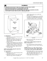
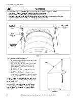
38. MIXING VALVE ASSEMBLY
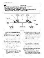
a. Hinge cabinet top or remove. Refer to
b. Remove screw holding mixing valve to
mounting bracket at rear of washer cabinet.
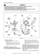
Refer to Figure 31.
NOTE: When installing mixing valve, tab on
bottom flange must be placed in positioning hole in
mounting bracket.
c. Pull mixing valve out toward front of washer
far enough to permit disconnecting water inlet
hoses from mixing valve.
d. Disconnect wires from mixing valve solenoids.
NOTE: Refer to appropriate wiring diagram when
rewiring solenoids.
39. WASHTUB AND CLOTHES GUARD
a. Remove agitator. Refer to Paragraph 25.
b. Hinge cabinet top or remove. Refer to
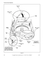
c. Disconnect filler hose from backflow
preventer. Refer to Figure 31.
NOTE: When installing filler hose, white line on
hose must be aligned with arrow on backflow
preventer. Refer to Figure 31. White line on hose
that connects to tub cover must be aligned with line
located on top side of outer tub cover. Refer to
Figure 31. Make sure the hose is in its natural
position (not kinked or twisted) and is parallel to the
rear edge of the washer cabinet. If it is not, loosen
hose clamp and straighten the hose.
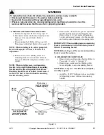
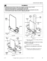
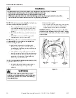
d. Unhook the pressure hose from the retainer
clips located on the left rear edge of the outer
tub cover. Refer to Figure 32.
Figure 31
Pressure
Hose
Water Inlet
Hose
Backflow
Preventer
Center
Line
Wire Harness
Clip
White
Line
Hose
Clamp
Filler
Hose
Line on
Tub Cover
Mixing Valve
Attaching
Screw


