33711
27
Section 5 Service Procedures
To reduce the risk of electric shock, fire, explosion, serious injury or death:
• Disconnect electric power to the washer before servicing.
• Never start the washer with any guards/panels removed.
• Whenever ground wires are removed during servicing, these ground wires must be
reconnected to ensure that the washer is properly grounded.
W003
WARNING
© Copyright, Alliance Laundry Systems LLC – DO NOT COPY or TRANSMIT
28. PUMP BELT
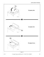
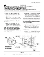
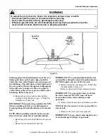
a. Remove two screws from bottom edge of front
panel. Refer to Figure 15.
b. Pull bottom of panel away from washer until
hold-down clips (located on top flange of
panel) disengage from slots in cabinet top.
Refer to Figure 15.
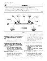
c. Loosen two front mounting screws and one rear
amounting screw holding pump and bracket to
washer base. Refer to Figure 16. Pivot entire
assembly toward motor to loosen belt tension.
d. Run belt off motor pulley, then remove belt
from pump pulley.
NOTE: After installing pump belt, adjust belt.
Refer to Paragraph 52.
29. DRIVE BELT
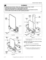
a. Remove two screws from bottom edge of front
panel. Refer to Figure 15.
b. Pull bottom of panel away from washer until
hold-down clips (located on top flange of
panel) disengage from slots in cabinet top.
Refer to Figure 15.
c. Loosen two front mounting screws and one rear
amounting screw holding pump and bracket to
washer base. Refer to Figure 16. Pivot entire
assembly toward motor to loosen belt tension.
d. Run belt off motor pulley, then remove belt
from pump pulley.
NOTE: After installing pump belt, adjust belt.
Refer to Paragraph 52.
e. Reach in through front of motor mount and
move idler lever to the left to release tension on
belt.
IMPORTANT: Use care when releasing the idler
lever tension. If the idler spring or helper spring is
overstretched, washer operation will be affected.
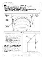
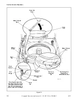
f. While holding idler lever, reach in and around
right side of motor and run belt off right side of
large drive pulley. Refer to Figure 17.
g. Remove belt from motor pulley and pull belt
out through front of motor mount.
Figure 15
Hold-Down
Clip
Front Panel
Screws
Figure 16
Pump
Belt
Pump
Attaching
Screws


