background image

28

33711

Section 5 Service Procedures

To reduce the risk of electric shock, fire, explosion, serious injury or death:
• Disconnect electric power to the washer before servicing.
• Never start the washer with any guards/panels removed.
• Whenever ground wires are removed during servicing, these ground wires must be 

reconnected to ensure that the washer is properly grounded.

W003

WARNING

© Copyright, Alliance Laundry Systems LLC – DO NOT COPY or TRANSMIT

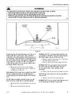
IMPORTANT: Drive belt MUST be replaced with 
belt No. 28808 (special clutch-type belt) for proper 
washer operation.

TO INSTALL NO. 28808 DRIVE BELT

NOTE: If the new belt is replacing a burned belt, 
the motor pulley “V” groove must be polished with 
a fine (320 grit) emery cloth to remove the rubber 
residue. The residue will affect the washer spin 
operation.

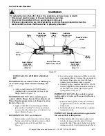
a. Push belt in through front of motor mount and 

place belt on motor pulley.

b. Reach in and around right side of motor, 

starting with belt on right side of large drive 
pulley, run belt onto pulley.

c. Reach in through front of motor mount and 

move idler lever to the left.

IMPORTANT: Use care when releasing the idler 
lever tension. If the idler spring or helper spring is 
overstretched, washer operation will be affected.

d. While holding idler lever, reach around right 

side of motor and place belt on idler pulley. 
IDLER PULLEY MUST RIDE ON OUTSIDE 
OF BELT.

NOTE: There is no belt adjustment after installing 
new drive belt. Check to be sure motor and 
mounting bracket have been shifted toward rear of 
washer to its limit of travel within the mounting 
bracket attaching screws. If the motor and 
mounting bracket must be repositioned, loosen the 
four motor attaching screws and shift motor and 
mounting bracket toward rear of washer to its limit 
of travel. Retighten the four attaching screws. Refer 
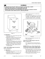
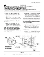
to Figure 17
.

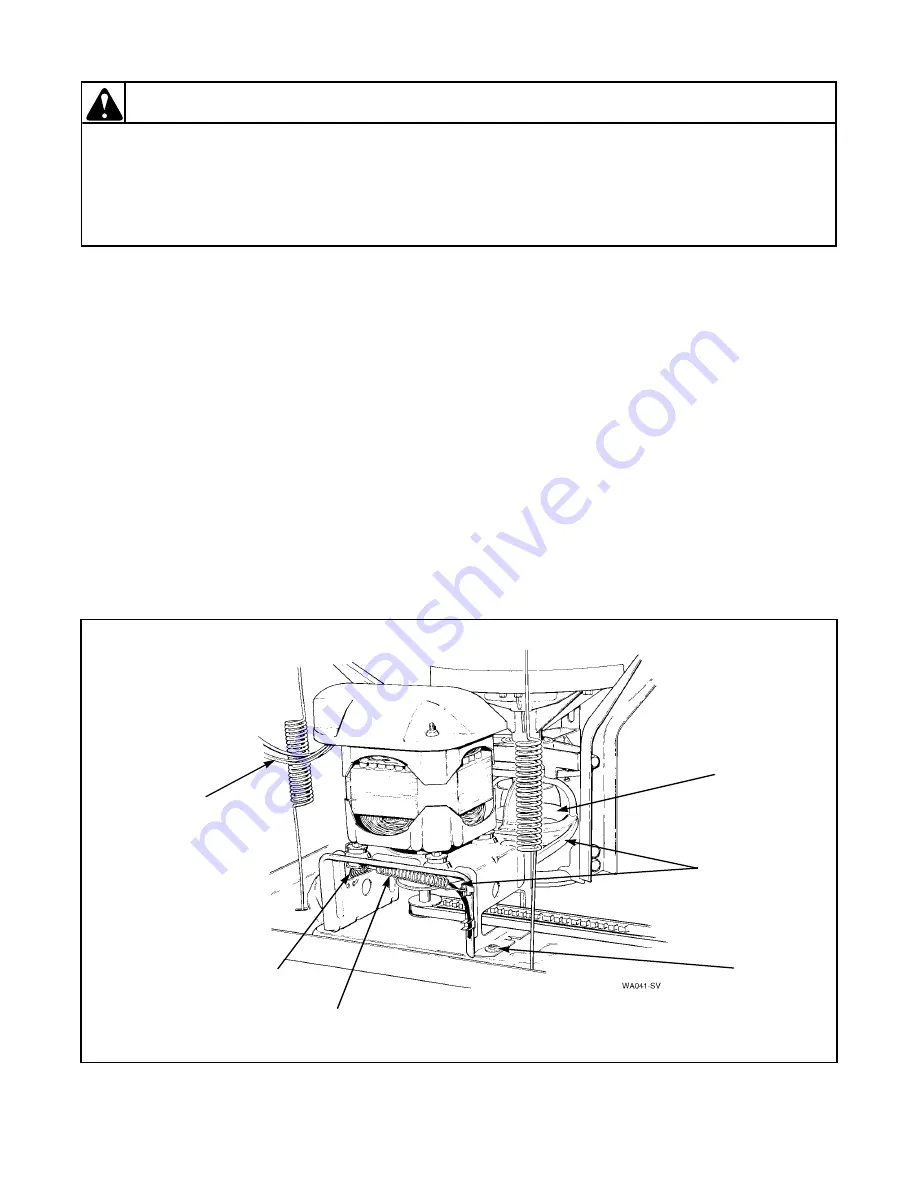
Figure 17

Motor

Attaching

Screws

Drive

Belt

Drive

Pulley

Idler

Spring

Helper
Spring

Wire harness 

must be installed 

ahead of spring.

Summary of Contents for AA3410

Page 1: ...www comlaundry com WA194 PT 1 Part No 33711R1 September 2002 Service Automatic Washers Refer to Page 6 for Model Numbers...

Page 2: ...Wire Harness to Top Left Rear Corner Gusset of Cabinet 17 17 Motor to Mounting Bracket 17 Section 5 Service Procedures 18 Control Hood Assembly 19 19 Electronic Control 19 20 Timer 21 21 Temperature...

Page 3: ...her Will Not Agitate Properly 87 73 Symptom Washer Will Not Spin Properly 88 Section 9 Cycle Sequence Charts Timer No 31238 Cycle Sequence Two Cycle 89 Timer No 31239 Cycle Sequence Three Cycle 90 Tim...

Page 4: ...ANT and NOTE are followed by specific instructions IMPORTANT The word IMPORTANT is used to inform the reader of specific procedures where minor machine damage will occur if the procedure is not follow...

Page 5: ...xpires Alliance Laundry Systems also recommends contacting an authorized technician and using authorized factory parts To reduce the risk of electric shock fire explosion serious injury or death Disco...

Page 6: ...from whom the machine was purchased or contact Alliance Laundry Systems at 920 748 3950 for the name and address of the nearest authorized parts distributor For technical assistance call 920 748 3121...

Page 7: ...TRANSMIT Model Identification Information in this manual is applicable to these washer models AA3410 AA8431 AWE852 AWM332 AWM551 AA4410 AA9431 AWE931 AWM351 AWM631 AA4411 NA3812 AWE951 AWM352 AWM651...

Page 8: ...ater supply is cold Check water heater Kinked hot water inlet hose Straighten or replace hose Clogged mixing valve screen or screen in outer end of inlet hose nearest water supply faucet Disconnect ho...

Page 9: ...d mixing valve screen or screen in outer end of inlet hose nearest water supply faucet Disconnect cold water inlet hose and clean or replace screen Inoperative cold water mixing valve solenoid Test so...

Page 10: ...lete valve A siphoning action started in washer will cause water to be siphoned from washer during cycle due to end of drain hose being lower than cabinet top of washer Drain hose fits tight in standp...

Page 11: ...or broken drive belt Adjust or replace belt Inoperative transmission assembly Repair or replace transmission assembly Sheared motor pulley roll pin Remove drive motor and replace roll pin and any oth...

Page 12: ...rive belt Adjust or replace belt Washer has gone OUT OF BALANCE LED Light Emitting Diode is flashing on the electronic control Open loading door to reset OUT OF BALANCE switch Rearrange load in washtu...

Page 13: ...oltage Contact local utility company or have a qualified electrician check power supply POSSIBLE CAUSE TO CORRECT Kinked drain hose Straighten hose Drain hose out of clamp in back of cabinet Remove wa...

Page 14: ...is properly grounded W003 WARNING Copyright Alliance Laundry Systems LLC DO NOT COPY or TRANSMIT 13 WATER LEAKING FROM OUTER TUB POSSIBLE CAUSE TO CORRECT Leaking water seal in outer tub Replace hub a...

Page 15: ...ust be reconnected to ensure that the washer is properly grounded W003 WARNING Copyright Alliance Laundry Systems LLC DO NOT COPY or TRANSMIT Section 4 Grounding 14 WALL RECEPTACLE POLARITY CHECK Figu...

Page 16: ...during servicing these ground wires must be reconnected to ensure that the washer is properly grounded W003 WARNING Copyright Alliance Laundry Systems LLC DO NOT COPY or TRANSMIT 15 POWER CORD TO CABI...

Page 17: ...er with any guards panels removed Whenever ground wires are removed during servicing these ground wires must be reconnected to ensure that the washer is properly grounded W003 WARNING Copyright Allian...

Page 18: ...nt parts and carefully remove components from control hood assembly NOTE Refer to appropriate wiring diagram when rewiring component parts TO REMOVE CONTROL HOOD END CAPS Remove end caps by carefully...

Page 19: ...2 AWM432 AWM452 AWM551 AND AWM531 Figure 6 Eaton Timer Screw End Cap Right Screw Screw End Cap Left Trim Strip Pressure Switch Control Hood Assembly Graphic Panel Clip Control Knob Assembly Timer Knob...

Page 20: ...repair timer d Disengage wire harness terminal block plug s from timer by pressing in on movable locking tabs located on each side of terminal block plug and pulling away from timer Refer to Figure 7...

Page 21: ...e hose 23 GRAPHIC PANEL Refer to Figure 5 or 6 a Remove six screws 3 on top and 3 at lower front holding hood assembly to control hood rear panel and cabinet top b Disconnect wires from component part...

Page 22: ...33711 23 Section 5 Service Procedures Copyright Alliance Laundry Systems LLC DO NOT COPY or TRANSMIT Figure 10 Procedure One Procedure Two Procedure Three Door Front Door Front Door Front...

Page 23: ...n the fin area damage to agitator may occur c Using a rocking motion back and forth carefully lift agitator off drive bell 26 AGITATOR DRIVE BELL AND SEAL ASSEMBLY a Open loading door b To remove agit...

Page 24: ...over the bell making sure indent on jaw lines up with wide slots on the bell Refer to Figure 13 g Screw the bolt down through hole in top of bell until bolt bottoms out in the hole in the transmission...

Page 25: ...bell over transmission shaft Rotate drive bell until splines in drive bell line up with splines on transmission shaft b Place No 294P4 Bell Tool over top of bell Screw bolt into transmission shaft un...

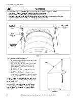
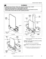
Page 26: ...pump belt adjust belt Refer to Paragraph 52 29 DRIVE BELT a Remove two screws from bottom edge of front panel Refer to Figure 15 b Pull bottom of panel away from washer until hold down clips located...

Page 27: ...ley b Reach in and around right side of motor starting with belt on right side of large drive pulley run belt onto pulley c Reach in through front of motor mount and move idler lever to the left IMPOR...

Page 28: ...bottom flange of mounting bracket must be placed in position hole in base Mounting bracket must be shifted toward rear of washer to its limit of travel within the mounting bracket attaching screws e...

Page 29: ...Switch Motor Pulley Pump Roll Pin Nut Helper Spring Locknut Idler Lever Washer Shoulder Bolt Clip Spring Motor Mounting Bracket Steel Washer Rubber Mount Spacer Rubber Mount Steel Washer Nut Ground W...

Page 30: ...external switch wires d Remove two screws holding switch to motor Refer to Figure 19 e Disconnect internal motor leads from switch terminals NOTE Refer to Wiring Schematics Section 9 for rewiring int...

Page 31: ...ull bottom of panel away from washer until hold down clips located on top flange of panel disengage from slots in cabinet top Refer to Figure 22 c Remove two cabinet top hold down screws Refer to Figu...

Page 32: ...brackets g Pull top forward far enough to permit disconnecting green ground wires from top left rear corner gusset of washer cabinet Disconnect wires from mixing valve solenoids at rear of washer NOT...

Page 33: ...re 26 e Slide the blade to the left to disengage the switch clip tab holding the switch to the switch holder Refer to Figure 26 f Disengage the opposite end of the switch clip tab from the holder and...

Page 34: ...Laundry Systems LLC DO NOT COPY or TRANSMIT k Reset the switch lever by raising and lowering the loading door NOTE Be sure the switch lever tab locates itself on top of the switch plunger l Reconnect...

Page 35: ...xing valve d Disconnect wires from mixing valve solenoids NOTE Refer to appropriate wiring diagram when rewiring solenoids 39 WASHTUB AND CLOTHES GUARD a Remove agitator Refer to Paragraph 25 b Hinge...

Page 36: ...r similar item to push the gasket down past the hold down clips Wipe or brush the top sealing surface of the outer tub flange and the sealing surface of the tub cover assembly and gasket to remove any...

Page 37: ...ch Funnel Area Bleach Funnel Bleach Funnel Tabs Outer Tub Outer Tub Cover Outer Tub Dimples Bleach Funnel Tabs Place fingers under this area and pull out and away from tub and at the same time lift up...

Page 38: ...ening screws to avoid chipping porcelain on washtub g Lift washtub and clothes guard out of outer tub IMPORTANT When removing washtub and clothes guard DO NOT lift up on clothes guard as you could dam...

Page 39: ...rear edge of the washer cabinet If it is not loosen hose clamp and straighten the hose f Unhook the pressure hose from the retainer clips located on the left rear edge of the outer tub cover Refer to...

Page 40: ...to hub Refer to Figure 34 Then lift washtub out of outer tub IMPORTANT When removing washtub DO NOT lift up on clothes guard as you could damage it Grasp top flange of washtub and remove from outer t...

Page 41: ...seal from bottom side of the seal until the sleeve is flush with bronze portion of the seal Refer to Figure 37 d Leave the garter spring on seal Place new seal over outer tub flange with seal lip on o...

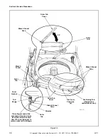
Page 42: ...cover place tub cover on outer tub at approximately a 45 degree angle with the positioning tab on cover fitting into the tub flange slot Refer to Figure 33 Make sure the two bleach funnel outlet tabs...

Page 43: ...oom the plastic bell h Place the agitator on top of the drive bell Slowly rotate the agitator until the fingers on the underside of agitator line up with the large slots on drive bell i A sharp blow o...

Page 44: ...the washer cabinet If it is not loosen hose clamp and straighten the hose e Locate the eight clip areas on the outer tub cover Using the 273P4 Tub Cover Tool insert the two prongs of the tool undernea...

Page 45: ...ur screws and washers holding washtub to hub Refer to Figure 34 IMPORTANT Porcelain Washtub Models Use care when tightening screws to avoid chipping porcelain on washtub g Lift washtub with clothes gu...

Page 46: ...etch the springs Mark the word FRONT on the front side of the outer tub so the complete tub module can be reinstalled in the same position o Disconnect hose between outer tub and pump assembly p Remov...

Page 47: ...el disengage from slots in cabinet top Refer to Figure 15 c Loosen two front mounting screws and loosen one rear mounting screw holding pump and bracket to washer base Refer to Figure 16 Pivot entire...

Page 48: ...stalling motor and mounting bracket positioning tab on right side of mounting bracket must be placed in positioning hole in base Mounting bracket must be shifted toward rear of washer to its limit of...

Page 49: ...r to Figure 44 NOTE Remove spring by turning in a COUNTERCLOCKWISE direction looking from lower end of input shaft of transmission assembly c Remove three screws holding brake pads rubber sleeves and...

Page 50: ...ph 35 d Remove agitator Refer to Paragraph 25 e Disconnect filler hose from backflow preventer Refer to Figure 31 NOTE When installing filler hose white line on hose must be aligned with arrow on back...

Page 51: ...he drive belt and a chipped idler pulley will damage belt We recommend that before removing or reinstalling the complete tub assembly you unhook idler spring and helper spring and move idler lever out...

Page 52: ...RING a Support bearing housing around outside diameter of bearing opening and carefully press bearing out of the housing b Clean all foreign material from inside diameter of bearing opening c Clean an...

Page 53: ...mately a 45 degree angle with the position tab on cover fitting into the tub flange slot Refer to Figure 33 Make sure the two bleach funnel outlet tabs are in the down position and are touching the in...

Page 54: ...o Disconnect hose between outer tub and pump assembly IMPORTANT Some water will always remain in outer tub Therefore before removing hose from pump pinch off or drain hose to prevent water spillage p...

Page 55: ...ransmission in vise so three of the eight screws holding transmission case and cover together are in the 12 4 and 7 o clock positions d Loosen three screws mentioned in step c approximately two turns...

Page 56: ...on Cover Assembly Dowel Pin Dowel Pin Slide Rack Agitator Pinion Transmission Case Assembly Washer Shaft Output Retainer Ring Transmission Oil 1 Fill Internal Gear Screw Washer Washer Special Screw Lo...

Page 57: ...slide IMPORTANT Never install a used internal gear in a new transmission case If transmission case and internal gear are to be reused be sure they are used as the original set h Refill transmission c...

Page 58: ...EARING ASSEMBLY a Remove transmission assembly Refer to Paragraph 45 steps a through r b Remove screws and lockwashers holding each support leg to outer tub Refer to Figure 42 c Lift complete pivot do...

Page 59: ...be applied IMPORTANT Do not allow any adhesive to get on the surface of the new pads that will be contacting the pivot dome of the tub module b Carefully align and apply the new snubber pad with fluf...

Page 60: ...through hole in cabinet top j Reconnect the filler hose to the backflow preventer Refer to Figure 31 NOTE When installing filler hose white line on hose must be aligned with arrow on backflow prevente...

Page 61: ...uards panels removed Whenever ground wires are removed during servicing these ground wires must be reconnected to ensure that the washer is properly grounded W003 WARNING Copyright Alliance Laundry Sy...

Page 62: ...s into washer base as far as possible b Turn appropriate leveling leg s out of base only until washer is level Keep washer as close to floor as possible IMPORTANT All four legs must rest firmly on flo...

Page 63: ...ased by turning screw COUNTERCLOCKWISE One quarter turn of the adjusting screw represents approximately one inch 2 54 cm increase or decrease of water level in washtub IMPORTANT DO NOT turn adjusting...

Page 64: ...re 1 1 2 pounds 675 kg to a point midway between pulleys Refer to Figure 55 d After belt tension is obtained tighten the three pump mounting bracket screws 53 OUT OF BALANCE SWITCH Refer to Figure 56...

Page 65: ...ed along with the wires TP Thermal Protector MS Motor Switch SW Start Winding HW High Winding LW Low Winding 55 TO CHECK CONTINUITY THROUGH BASE HARNESS CONTROL HARNESS AND TIMER FOR MOTOR START CIRCU...

Page 66: ...e washer is properly grounded W003 WARNING Copyright Alliance Laundry Systems LLC DO NOT COPY or TRANSMIT 56 G E MOTOR CHECK Start Windings OPEN Start windings defective replace motor Set Ohmmeter to...

Page 67: ...witch OPEN Remove white motor wire Remove B switch terminal Check from end of white wire to yellow 8 3 to 4 Ohms Low windings OK Remove white motor wire Check from pink A to B terminal OPEN Low windin...

Page 68: ...polarized three slot effectively grounded receptacle rated 110 120 Volts AC alternating current Refer to Figure 58 Do not operate other appliances on the same circuit Do not overload circuits Refer to...

Page 69: ...utlet installed by a qualified electrician If a positive ground cannot be established through the power cord and local code permits its use connect an external ground wire 18 gauge minimum available a...

Page 70: ...gher water level is desired move the control to RESET then make your water level selection NOTE When the control is released it should not remain at the RESET position IMPORTANT Holding the LOAD SIZE...

Page 71: ...which of these cycles are available NOTE When you have selected a cycle you will see a number light up in the display area This number indicates the length of the wash cycle When the GO pad is presse...

Page 72: ...NITS cycles and during periods of soaking Digital Display Shows you the length of the wash cycle you have selected and counts down the number of minutes excluding water fills remaining in the cycle Th...

Page 73: ...0 40 45 55 60 85 Figure 62 WASH TIME When a cycle is selected the NORMAL WASH TIME is automatically provided The number of minutes in the wash portion of the cycle on the NORMAL WASH TIME setting appe...

Page 74: ...produce the softest tone Press the pad again and the tone will get louder Pressing the pad a third time will result in setting the loudest tone To turn the signal off press the pad repeatedly until th...

Page 75: ...the h flashes The flashing h tells you the washer has started to count down the time When the selected number of hours has passed the washer will start and perform the cycle you selected Pressing ADVA...

Page 76: ...s to one of the symptoms detailed on the following pages proceed to that flow chart The diagnostic cycle chart check does not have to be made Self Diagnostic Routine Entry Follow the sequence given be...

Page 77: ...n loading door for four seconds 3 Unplug washer NOTE 1 This test routine will only light LED s pertaining to hardware model selected 2 When last step in table is finished routing sequence will repeat...

Page 78: ...f Off 66 Spin Agitate Off Off Off Off 55 Delay Start Agitate Off Off Off Off 44 Memory Agitate Off Off Off Off 33 Auto Prewash Agitate Off Off Off Off 22 Extra Rinse Agitate Off Off Off Off 11 Signal...

Page 79: ...PTOMS NOTE If when trying to start Diagnostic Cycle LED display flashes but does not start check the following 1 Is loading door closed 2 Loading door switch operating properly 3 Is washer plugged int...

Page 80: ...ity reversed at outlet Refer to Paragraph 58 NO YES Consult electrician Washer effectively grounded Refer to Paragraph 58 120 Volts between terminals N O on motor relay K3 and P1 neutral with the load...

Page 81: ...with a digital multi meter set on 200 Ohm scale Approximately 120 Volts between P4 and P1 neutral and 120 Volts between P5 and P1 neutral NO YES Unplug power cord Disconnect P1 P4 and P5 terminals on...

Page 82: ...t must be taken with a digital multi meter set on 200 Ohm scale Tripped circuit breaker or blown fuse NO YES Unplug power cord Disconnect terminals P1 P4 and P5 on control Reset circuit breaker or rep...

Page 83: ...e to ensure that pressure switch has reset Use ADVANCE TIMER pad to advance cycle to SPIN if necessary NOTE Both hot water relay K4 and cold water relay K5 are energized for warm water fill Only hot w...

Page 84: ...operly Broken loose or incorrect wiring YES By pass pressure switch to allow agitation without water in washtub With power cord unplugged remove and insulate wire from terminal P6 on control YES NO Co...

Page 85: ...LL NOT SPIN PROPERLY Washer will not spin properly Broken loose or incorrect wiring YES NO YES Correct wiring Loading Door Switch 120 Volts between terminal N O on motor relay K3 and P1 neutral with l...

Page 86: ...00 27 63 PAUSE FAST 1 14 6 76 1 13 6 72 SPIN FAST 7 00 38 39 6 47 37 49 OFF 2 00 10 97 2 09 10 96 PERMANENT PRESS 26 13 PLUS FILL WASH FILL or AGITATE H W C FAST 9 00 49 35 9 00 49 74 PAUSE FAST 1 14...

Page 87: ...LOW 45 2 73 45 2 76 WASH FILL or SOAK H W C 2 00 7 29 2 00 7 37 WASH FILL or AGITATE H W C SLOW 45 2 73 45 2 73 PAUSE Soak 1 50 6 68 1 49 6 69 COOL DOWN Press Sw Controlled SPIN Partial Drain SLOW 45...

Page 88: ...W 4 27 10 13 SPIN and BUZZER 03 11 OFF BUZZER Timer Motor Runs Timer Motor Runs 1 00 30 2 30 2 28 1 14 5 69 ON SINGLE SPEED MODEL WASHERS ALL SPEEDS ARE FAST SOAK IS INFINITE PREWASH IS 24 37 PLUS FIL...

Page 89: ...FILL COLD Variable PAUSE 1 32 4 22 SPIN SLOW 1 30 4 14 SPIN and SPRAY COLD SLOW 50 2 29 SPIN SLOW 1 35 4 36 PAUSE 30 1 38 RINSE FILL Timer Motor Runs COLD 1 20 3 67 PAUSE or FILL COLD 21 97 RINSE FILL...

Page 90: ...HOICE 1 35 3 62 PAUSE 29 1 09 RINSE FILL Timer Motor Runs COLD 1 22 3 12 PAUSE or FILL COLD 28 1 05 RINSE FILL or AGITATE COLD SLOW 2 30 5 69 PAUSE 2 19 5 28 SPIN CHOICE 4 30 10 25 OFF Timer Motor Run...

Page 91: ...N 6 00 FUNCTION ONLY ENTERS CYCLE WHEN SELECTED IF AVAILABLE TIME WILL VARY DEPENDING ON SELECTION THIS TIME WILL BE 3 00 WHEN EXTRA RINSE IS SELECTED KEY H HOT W WARM C COLD Cycle Function Water Temp...

Page 92: ...RS CYCLE WHEN SELECTED IF AVAILABLE TIME WILL VARY DEPENDING ON SELECTION THIS TIME WILL BE 3 00 WHEN EXTRA RINSE IS SELECTED KEY H HOT W WARM C COLD Cycle Function Water Temp Time DELICATE DELAY 0 TO...

Page 93: ...W003 WARNING Copyright Alliance Laundry Systems LLC DO NOT COPY or TRANSMIT Section 10 Internal Wiring of Washer Motor Switch 27658P MOTOR ASSEMBLY 1 SPEED MOTORS White Red Yellow Blue Brown Orange Ye...

Page 94: ...grounded W003 WARNING Copyright Alliance Laundry Systems LLC DO NOT COPY or TRANSMIT 27179P MOTOR ASSEMBLY 2 SPEED MOTORS Red Brown White Yellow Blue Red Orange Black Blue White Yellow Violet Overloa...

Page 95: ...s instructions may result in conditions which can produce bodily injury and or property damage W030 WARNING Copyright Alliance Laundry Systems LLC DO NOT COPY or TRANSMIT Section 11 Wiring Diagrams WI...

Page 96: ...perate this machine according to the manufacturer s instructions may result in conditions which can produce bodily injury and or property damage W030 WARNING Copyright Alliance Laundry Systems LLC DO...

Page 97: ...ntain and or operate this machine according to the manufacturer s instructions may result in conditions which can produce bodily injury and or property damage W030 WARNING Copyright Alliance Laundry S...

Page 98: ...n and or operate this machine according to the manufacturer s instructions may result in conditions which can produce bodily injury and or property damage W030 WARNING Copyright Alliance Laundry Syste...

Page 99: ...te this machine according to the manufacturer s instructions may result in conditions which can produce bodily injury and or property damage W030 WARNING Copyright Alliance Laundry Systems LLC DO NOT...

Page 100: ...n and or operate this machine according to the manufacturer s instructions may result in conditions which can produce bodily injury and or property damage W030 WARNING Copyright Alliance Laundry Syste...

Page 101: ...ntain and or operate this machine according to the manufacturer s instructions may result in conditions which can produce bodily injury and or property damage W030 WARNING Copyright Alliance Laundry S...

Page 102: ...ntain and or operate this machine according to the manufacturer s instructions may result in conditions which can produce bodily injury and or property damage W030 WARNING Copyright Alliance Laundry S...

Page 103: ...ntain and or operate this machine according to the manufacturer s instructions may result in conditions which can produce bodily injury and or property damage W030 WARNING Copyright Alliance Laundry S...

Reviews: