33711
51
Section 5 Service Procedures
To reduce the risk of electric shock, fire, explosion, serious injury or death:
• Disconnect electric power to the washer before servicing.
• Never start the washer with any guards/panels removed.
• Whenever ground wires are removed during servicing, these ground wires must be
reconnected to ensure that the washer is properly grounded.
W003
WARNING
© Copyright, Alliance Laundry Systems LLC – DO NOT COPY or TRANSMIT
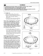
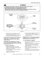
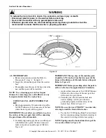
IMPORTANT: When installing spring, be sure it is
inserted into groove in large splines of lower
transmission tube. Use tool, No. 242P4, for installing
the spring.
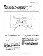
d. After brake is installed, put the washer through
the following check to make sure the brake is
operating properly.
(1) Turn off the electrical power to the washer.
(2) Turn the drive pulley one complete
revolution in the agitation direction, then
push the drive pulley up against the brake.
(3) Check for a .030 minimum gap between the
drive pulley and the helix ramp surfaces.
IMPORTANT: If the gap is less than .030, the brake
may not stop the washtub from spinning in the
required seven seconds because the brake will not
close properly.
(4) Turn on the electrical power to the washer
and start the washer in the final spin.
NOTE: After the washtub has been spinning for two
minutes, the normal spin speed should be
approximately 580 R.P.M. If not, the cause could be
dragging brake pads. If problems occur with steps 3
or 4, remove the brake assembly and correct the
problem.
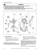
44. LOWER BEARING HOUSING
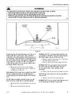
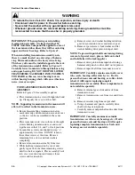
a. Remove two screws from bottom edge of front
panel. Refer to Figure 15.
b. Pull bottom of panel away from washer until
hold-down clips (located on top flange of
panel) disengage from slots in cabinet top.
Refer to Figure 15.
c. Remove two cabinet top hold-down screws and
hinge cabinet top or remove. Refer to
Paragraph 35.
d. Remove agitator. Refer to Paragraph 25.
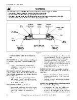
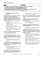
e. Disconnect filler hose from backflow
preventer. Refer to Figure 31.
NOTE: When installing filler hose, white line on
hose must be aligned with arrow on backflow
preventer. Refer to Figure 31. White line on hose
that connects to tub cover must be aligned with line
located on top side of outer tub cover. Refer to
Figure 31. Make sure the hose is in its natural
position (not kinked or twisted) and is parallel to the
rear edge of the washer cabinet. If it is not, loosen
hose clamp and straighten the hose.
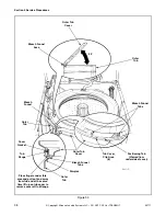
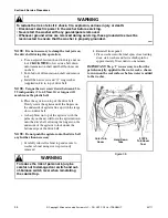
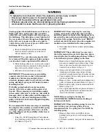
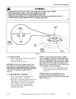
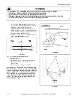
f. Locate the eight clip areas on the outer tub
cover. Refer to Figure 33. Insert your fingers
under this clip area of the cover edge. Refer to
Figure 33. One by one, disengage each clip
from the tub flange by pulling the tub cover
edge out and away from the outer tub and lifting
on the cover at the same time. Do this around
the entire tub cover until the cover is free from
the outer tub flange.
NOTE: When installing outer tub cover, always use
a new cover gasket. The gasket must be inserted into
the bottom of the groove (past the hold-down clips)
in the underside of the tub cover. This may require
using a piece of dowel, wooden pencil or similar
item to push the gasket down past the hold-down
clips.
Wipe or brush the top sealing surface of the outer
tub flange and the sealing surface of the tub cover
assembly and gasket to remove any foreign
materials.
Starting at the bleach funnel area of the tub cover,
place tub cover on outer tub at approximately a 45
degree angle with the position tab on cover fitting
into the tub flange slot. Refer to Figure 33.
Make sure the two bleach funnel outlet tabs are in
the down position and are touching the inside
surface of the outer tub. These tabs can be located
by viewing through the two square holes in the
bleach funnel area of the tub cover. If the bleach
funnel tabs are not down, place a small screwdriver
through the square holes in the bleach funnel area
and push the tabs downward. Refer to Figure 33.


