background image

www.alliancelaundry.com

CHM1772

CHM1772C

Part No. F8266301ENR4

December 2016

Washer-Extractor

Cabinet Hardmount

Refer to Page 8 for Model Numbers

T

roubleshooting

Summary of Contents for CCN020HNF

Page 1: ...www alliancelaundry com CHM1772 CHM1772C Part No F8266301ENR4 December 2016 Washer Extractor Cabinet Hardmount Refer to Page 8 for Model Numbers Troubleshooting...

Page 2: ......

Page 3: ...eshooting 13 2 Speed Models 14 1 No Extract 14 2 No Basket Rotation 16 Design 1 Only 17 1 No External Supplies 17 2 No Extract F and V speed Models 19 3 No Rotation without Drive Fault 20 Design 1 2 a...

Page 4: ...ion Error Sheet 1 of 8 59 2 Ed02 DC BUS Error Sheet 1 of 2 67 3 Ed03 Tachometer Error Sheet 1 of 2 69 4 Ed04 Locked Rotor Error Sheet 1 of 2 71 5 Ed05 IGBT Overcurrent Error Sheet 1 of 2 73 6 Ed06 The...

Page 5: ...d WARNING Caution indicates the presence of a hazard that will or can cause minor personal injury or property damage if the caution is ignored CAUTION Failure to install maintain and or operate this p...

Page 6: ...ce any part of the washer or attempt any servicing unless specifically recommended in the user maintenance instructions or in published user repair instructions that the user understands and has the s...

Page 7: ...ING and IMPORTANT SAFETY INSTRUCTIONS appearing in this manual are not meant to cover all possible conditions and situations that may occur Common sense caution and care must be exercised when install...

Page 8: ...operation of the machine a Attempt to start the machine with the door open The machine should not start with the door open b Close the door without locking it and attempt to start the machine The mach...

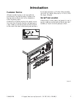
Page 9: ...ing about your product be sure to mention model and serial numbers Model and serial numbers are located on serial plate s as shown CHM3025P CHM3025P C N03 0G CUOU00 1 00 00 00 00 00 0 20 8 24 0 3 Hz H...

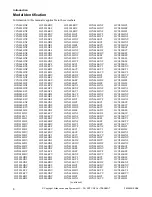
Page 10: ...20HNV HCN020HXF HCN020HY2 HCN020HYF HCN020KC2 HCN020KCF HCN020KCV HCN020KD2 HCN020KDF HCN020KDV HCN020KEF HCN020KEV HCN020KX2 HCN020KXF HCN020KY2 HCN020KYF HCN020KYV HCN030HC2 HCN030HCF HCN030HD2 HCN0...

Page 11: ...SCD040LD2 SCD040LDF SCD040LDV SCD060JDF SCD060LD2 SCD060LDF SCD060LDV SCD080LDF SCD080LDV SCL020HN2 SCL020HNF SCL020HNV SCL020JC2 SCL020JCF SCL020JCV SCL020JD2 SCL020JDF SCL020JDV SCL020JE2 SCL020JEF...

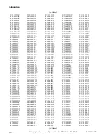
Page 12: ...V SCN040WD2 SCN040WDF SCN040WDV SCN040WE2 SCN040WEF SCN040WEV SCN040WX2 SCN040WY2 SCN040WYF SCN040WYV SCN060HN2 SCN060HNF SCN060HNV SCN060JC2 SCN060JCF SCN060JCV SCN060JD2 SCN060JDF SCN060JEF SCN060JX...

Page 13: ...V SCU080WXV SCU080WYV SCU125KNV SCY020JDV SCY020JEF SCY020KNF SCY020KNV SCY020LEV SCY020WEV SCY030JDV SCY030JEF SCY030KNF SCY030KNV SCY030LEV SCY030WEV SCY040JDV SCY040JEF SCY040KNF SCY040KNV SCY040LE...

Page 14: ...r dry supplies The supply dispenser s nozzles flush the compartments with water at the appropriate times throughout a cycle Wash The basket includes ribs that lift the laundry from the wash water The...

Page 15: ...nect electrical power to the washer extractor before servicing it Close the gas shut off valve to the washer extractor when applicable before servicing it Never start the washer extractor with any gua...

Page 16: ...T3 on contactor check motor and wiring to motor No Refer to No Outputs flowchart No 1 Verify J16 plug is intact 2 Verify that there is continuity through NC contacts on FWD and REV contactors KM3 and...

Page 17: ...Copyright Alliance Laundry Systems LLC DO NOT COPY or TRANSMIT 2 Speed Models 15 F8266301ENR4 No Extract NOTE Refer to the wiring diagram supplied with your machine CHM498S A B CHM498S...

Page 18: ...voltage present at contactor coil Troubleshoot AP1 Output Board Repair replace contactor as necessary No Is the proper voltage present at L1 L2 and L3 on the contactor Yes No Yes Troubleshoot why vol...

Page 19: ...plies Is the parameter set to C Set the parameter SUPC to S Yes Is the ribbon cable between H10 on AP1 Output Board and RB1 on AP4 Auxiliary Output Supply Board connected and in good shape Re connect...

Page 20: ...Copyright Alliance Laundry Systems LLC DO NOT COPY or TRANSMIT Design 1 Only F8266301ENR4 18 No External Supplies NOTE Refer to the wiring diagram supplied with your machine CHM498S CHM498S A B...

Page 21: ...Correct voltage at the drive No No Are any of the drive output LEDs RUN REV SPD1 SPD2 or SPD3 lit on the AP1 Output Board Yes Check H13 and J16 Check wiring between AP2 Control Logic Board and AP1 Ou...

Page 22: ...ulleys are engaged on shafts Yes Is the correct voltage present at the drive No Trace wires back to source to find where voltage is lost No Is the display active on the drive Re check supply voltage a...

Page 23: ...Copyright Alliance Laundry Systems LLC DO NOT COPY or TRANSMIT Design 1 Only 21 F8266301ENR4 No Rotation without Drive Fault CHM559S A B...

Page 24: ...61S dOOr Displayed at Startup or When Vend Satisfied Is door handle fully engaged Fully latch door No Is magnet present on door Yes Replace magnet No Is J15 plug fully engaged Yes Firmly seat plug No...

Page 25: ...lliance Laundry Systems LLC DO NOT COPY or TRANSMIT Design 1 2 and 3 23 F8266301ENR4 dOOr Displayed at Startup or When Vend Satisfied NOTE Refer to the wiring diagram supplied with your machine CHM504...

Page 26: ...Yes Yes Yes Design 1 and 2 with auxiliary heat Check for continuity through SP1a empty level pressure switch Design 2 with out auxiliary heat Repair replace jumper If SP1a is open Pressure switch bad...

Page 27: ...yright Alliance Laundry Systems LLC DO NOT COPY or TRANSMIT Design 1 2 and 3 25 F8266301ENR4 Door Does Not Lock at Startup NOTE Refer to the wiring diagram supplied with your machine CHM504 CHM504S A...

Page 28: ...ails to Unlock at End of the Cycle Is the solenoid mechanically bound Replace adjust solenoid as necessary Yes Is there continuity through low level water pressure switch Unless the machine is rotatin...

Page 29: ...t Alliance Laundry Systems LLC DO NOT COPY or TRANSMIT Design 1 2 and 3 27 F8266301ENR4 Door Fails to Unlock at End of the Cycle NOTE Refer to the wiring diagram supplied with your machine CHM504S CHM...

Page 30: ...items Yes Add or remove items as needed to ensure proper mix of items e g do not wash towels and sheets together No Are the anchor bolts and nuts properly torqued Yes Tighten all anchor bolts and nuts...

Page 31: ...tor grouted properly Properly grout washer extractor Refer to Installation Manual for specifications No Yes Yes Remove and re install washer extractor correctly Refer to Installation Manual for specif...

Page 32: ...the J30 plug fully inserted Fully insert J30 plug No Is there 220V present at H2 1 to H2 14 and H2 1 to H2 15 on AP1 output board Yes Re check for voltage at valves and ensure wiring and Molex plugs a...

Page 33: ...right Alliance Laundry Systems LLC DO NOT COPY or TRANSMIT Design 1 2 and 3 31 F8266301ENR4 Machine Does Not Fill with Water NOTE Refer to the wiring diagram supplied with your machine CHM50 A B C CHM...

Page 34: ...rom H3 18 to H3 5 Yes Verify H1 H3 harness is intact No Is harness in good condition Yes Replace repair harness as necessary No No Replace AP2 Control Logic Board Yes B Check for 208 240VAC at H9 3 an...

Page 35: ...Copyright Alliance Laundry Systems LLC DO NOT COPY or TRANSMIT Design 1 2 and 3 33 F8266301ENR4 No Display Sheet 1 of 2 NOTE Refer to the wiring diagram supplied with your machine CHM50 CHM503S A...

Page 36: ...Copyright Alliance Laundry Systems LLC DO NOT COPY or TRANSMIT Design 1 2 and 3 F8266301ENR4 34 No Display Sheet 2 of 2 NOTE Refer to the wiring diagram supplied with your machine CHM50 CHM502S B C...

Page 37: ...ed Verify INTLCK LED and MAIN PWR LED are lit on the AP1 Output Board Determine why SQ1 door closed and SQ2 door locked are not closing Adjust switches as necessary Yes No Is there 220VAC between both...

Page 38: ...Copyright Alliance Laundry Systems LLC DO NOT COPY or TRANSMIT Design 1 2 and 3 F8266301ENR4 36 No Outputs Sheet 1 of 3 NOTE Refer to the wiring diagram supplied with your machine CHM504S CHM504S B...

Page 39: ...Copyright Alliance Laundry Systems LLC DO NOT COPY or TRANSMIT Design 1 2 and 3 37 F8266301ENR4 No Outputs Sheet 2 of 3 NOTE Refer to the wiring diagram supplied with your machine CHM503 CHM503S B C A...

Page 40: ...Copyright Alliance Laundry Systems LLC DO NOT COPY or TRANSMIT Design 1 2 and 3 F8266301ENR4 38 No Outputs Sheet 3 of 3 NOTE Refer to the wiring diagram supplied with your machine CHM498S CHM498S A...

Page 41: ...Yes Is the machine slow to fill No Check audit data for fill and drain times Check water pressure and or check for clogged screens in fill hoses Yes Check level switch and associated hoses for obstruc...

Page 42: ...4 40 9 No Keypad Function CHM4 No Keypad Function Is the display on Refer to No Display flowchart No Is keypad ribbon cable from keypad to AP2 Control Logic Board plugged in Yes Plug the keypad ribbon...

Page 43: ...ity jumper configuration at H14 on the AP1 Output Board incorrect Use capacity information on schematic to select correct jumper Refer to Abnormal Conditions Schematic Yes Check pressure hose connecti...

Page 44: ...right Alliance Laundry Systems LLC DO NOT COPY or TRANSMIT Design 1 2 and 3 F8266301ENR4 42 Abnormal Operation 20 100 Pound Models Sheet 1 of 2 NOTE Refer to the wiring diagram supplied with your mach...

Page 45: ...lliance Laundry Systems LLC DO NOT COPY or TRANSMIT Design 1 2 and 3 43 F8266301ENR4 Abnormal Operation 125 Pound Models Sheet 2 of 2 NOTE Refer to the wiring diagram supplied with your machine CHM511...

Page 46: ...gn 1 2 and 3 F8266301ENR4 44 11 No High Extract CHM474 No High Extract Is the machine properly loaded Properly load machine No Is the machine oversudsing Reduce soap usage during wash cycle Yes Yes Ru...

Page 47: ...pyright Alliance Laundry Systems LLC DO NOT COPY or TRANSMIT Design 1 2 and 3 45 F8266301ENR4 No Extract F and V speed Models NOTE Refer to the wiring diagram supplied with your machine CHM499S CHM499...

Page 48: ...with Drive Fault Is there an active fault on the inverter drive Determine what the fault is and act accordingly Refer to Inverter Drive Supplement Refer to No Motor Rotation without Drive Fault flowch...

Page 49: ...rated Inspect wiring and access panel switch Repair replace as necessary No NOTE If unable to enter Manual Programming Manual Diagnostics and Manual Rapid Advance make sure they are not disabled in PD...

Page 50: ...right Alliance Laundry Systems LLC DO NOT COPY or TRANSMIT Design 1 2 and 3 F8266301ENR4 48 Unable to Access Manual Mode NOTE Refer to the wiring diagram supplied with your machine CHM501S CHM501S A B...

Page 51: ...ENR4 14 EFS Error CH E FS Error Is the jumper in place at J28 2 to J28 1 Replace jumper No Is there 5VDC between H12 3 and H12 1 on AP1 Output Board Frame balance jumper circuit is open Inspect wiring...

Page 52: ...Copyright Alliance Laundry Systems LLC DO NOT COPY or TRANSMIT Design 1 2 and 3 F8266301ENR4 50 EFS Error NOTE Refer to the wiring diagram supplied with your machine CHM499S CHM499S A B...

Page 53: ...er in the machine No Refer to Machine Does Not Fill with Water flowchart No Is there 220V at H7 2 and H7 5 when the heater output is on Yes Yes Refer to No Outputs flowchart No For Steam Machines 1 Ch...

Page 54: ...Copyright Alliance Laundry Systems LLC DO NOT COPY or TRANSMIT Design 1 2 and 3 F8266301ENR4 52 Heat Error Machines with Auxiliary Heat Only CHM558S A...

Page 55: ...Copyright Alliance Laundry Systems LLC DO NOT COPY or TRANSMIT Design 1 2 and 3 53 F8266301ENR4 Heat Error Machines with Auxiliary Heat Only CHM557S B...

Page 56: ...Copyright Alliance Laundry Systems LLC DO NOT COPY or TRANSMIT Design 1 2 and 3 F8266301ENR4 54 Heat Error Machines with Auxiliary Heat Only CHM556S C...

Page 57: ...in vault switch If coin box is too short either install longer box or manually depress switch No Is J23 plug fully inserted and in good condition Repair replace J23 plug as neccessary No Yes Is there...

Page 58: ...ght Alliance Laundry Systems LLC DO NOT COPY or TRANSMIT Design 1 2 and 3 F8266301ENR4 56 Control Always in Audit Display Mode NOTE Refer to the wiring diagram supplied with your machine CHM501S CHM50...

Page 59: ...g Possible comm port chosen on the PDA Search the ports on the PDA to find correct port for IR Yes Is the AP1 Output Board or AP2 Control Logic Board properly grounded No Check for ground to the AP2 c...

Page 60: ...DO NOT COPY or TRANSMIT Design 1 2 and 3 F8266301ENR4 58 Control Will Not Allow PDA to Download a Machine Cycle it is Currently Running PHM2098S 1 AP1 Chassis Tab making contact with the ground pad 2...

Page 61: ...ut power to the drive Power up and try again Yes Are the connectors tight on the H 5 plug on the inverter drive and H 9 on the Front End Control Tighten connectors and power machine back on No No Cont...

Page 62: ...e on H1 4 H1 3 and H1 1 and single phase line voltage on H1 4 and H1 3 For B voltage only is there line voltage on H1 1 and H1 2 Replace Inverter control Board Yes Replace or fix the necessary harness...

Page 63: ...chines main power supply No Yes Yes Is there voltage on the KM1 contactor between A1 Blu org and A2 Gry Wht wire Replace contactor Replace drive No Check to see if the drive is blowing the fuse Yes No...

Page 64: ...EN HEARTBEAT LED BLINKS 1 SEC ON 1 SEC OFF WHEN CONTROL IS POWERED GREEN STEADY ON LED INDICATES DRIVE LOGIC HAS POWER RED FLASHING LED INDICATES DRIVE IS COMMUNICATING RED LEDS INDICATES THE DC BUS I...

Page 65: ...D SHOWS COMMUNICATION WITH MAIN CONTROL RED LED INDICATES THE DC BUS IS CHARGED HB_GREEN O LED1 PS_GREEN O LED2 ER_RED O LED3 H5_6 H5_5 H5_4 H5_3 H5_2 H5_1 H3_2 H5 _ 3 H5 _ 5 H3_4 H3_3 YEL J36_1 YEL Y...

Page 66: ...OL RED LED INDICATES THE DC BUS IS CHARGED HB_GREEN O LED1 PS_GREEN O LED2 ER_RED O LED3 H5_6 H5_5 H5_4 H5_3 H5_2 H5_1 H3_2 H5_3 H5 _ 5 H3_1 H2_5 YEL J36_1 YEL YEL J36_2 YEL BLU ORG J34 _ 1 BLU ORG GR...

Page 67: ...NICATION WITH MAIN CONTROL RED LED INDICATES THE DC BUS IS CHARGED HB_GREEN O LED1 PS_GREEN O LED2 ER_RED O LED3 H5_6 H5_5 H5_4 H5_3 H5_2 H5_1 H3_2 H5_3 H5_5 H3_4 H3_3 YEL J36_1 YEL YEL J36_2 YEL BLU...

Page 68: ...IVE KM1 H5 J3 J5 J34 ELECTRIC HEAT MODELS ONLY SEE ELECTRIC HEAT OPTION WIRING DIAGRAM SEE VOLTAGE OPTION DIAGRAM FOR ADDITIONAL DRIVE AND CONTACTOR WIRING 1 5 4 6 2 3 1 5 4 6 2 3 T1 1 2 1 2 3 4 1 2 3...

Page 69: ...a qualified electrician to correct the problem No No Yes Yes Yes Does the error only happen at the start of a spin cycle If problem persists replace inverter control board Replace motor No Move high l...

Page 70: ...NPUT TERMINAL BLOCK SEE ELECTRIC HEAT DIAGRAM FOR HEATER CONNECTIONS L1 L1 L1 BLK L1 L1 L1 BLK L2 L2 L2 WHT L2 L2 L2 WHT L3 L3 L3 RED QF1 CIRCUIT BREAKER 25A L3 L3 L3 RED P E GROUND TERMINAL SERVICE C...

Page 71: ...to H3 on drive and tachometer connections on motor Power up and try again Yes No No While spinning the basket manually check for multiple pulses of continuity between the 2 yellow wires on the H3 2 a...

Page 72: ...RED LED INDICATES THE DC BUS IS CHARGED HB_GREEN O LED1 PS_GREEN O LED2 ER_RED O LED3 H5_6 H5_5 H5_4 H5_3 H5_2 H5_1 H3_2 H5_3 H5_5 H3_1 H2_5 YEL J36_1 YEL YEL J36_2 YEL BLU ORG J34 _ 1 BLU ORG GRY WHT...

Page 73: ...e motor windings Continuity should be uniform between Are windings uniform 1 L1 and L2 Black to White 2 L2 and L3 White to Red 3 L1 and L3 Black to Red Replace motor If problem persists after changing...

Page 74: ...L RED LED INDICATES THE DC BUS IS CHARGED HB_GREEN O LED1 PS_GREEN O LED2 ER_RED O LED3 H5_6 H5_5 H5_4 H5_3 H5_2 H5_1 H3_2 H5_3 H5_5 H3_1 H2_5 YEL J36_1 YEL YEL J36_2 YEL BLU ORG J34 _ 1 BLU ORG GRY W...

Page 75: ...e motor phase to phase windings Continuity should be uniform between Are windings uniform 1 L1 and L2 Black to White 2 L2 and L3 White to Red 3 L1 and L3 Black to Red No A Yes Check the motor phase to...

Page 76: ...L RED LED INDICATES THE DC BUS IS CHARGED HB_GREEN O LED1 PS_GREEN O LED2 ER_RED O LED3 H5_6 H5_5 H5_4 H5_3 H5_2 H5_1 H3 _ 2 H5_3 H5_5 H3_1 H2_5 YEL J36_1 YEL YEL J36_2 YEL BLU ORG J34 _ 1 BLU ORG GRY...

Page 77: ...6 Thermal Error CHM537S Power down Are there any obstructions preventing convection of heat off the drive heatsink Clean out lint or obstruction If problem continues after cycling power and allowing t...

Page 78: ...own power up and try again Is the correct inverter installed in the machine Power machine down Are there any loose connections Verify the correct size and voltage inverter is installed No Repair conne...

Page 79: ...windings Continuity should be uniform between Are windings uniform 1 L1 and L2 Black to White 2 L2 and L3 White to Red 3 L1 and L3 Black to Red No A Does the basket move freely Check to make sure bea...

Page 80: ...OL RED LED INDICATES THE DC BUS IS CHARGED HB_GREEN O LED1 PS_GREEN O LED2 ER_RED O LED3 H5_6 H5_5 H5_4 H5_3 H5_2 H5_1 H3_2 H5_3 H5_5 H3_1 H2_5 YEL J36_1 YEL YEL J36_2 YEL BLU ORG J34 _ 1 BLU ORG GRY...

Page 81: ...rrent Sensor Error CHM535S Power down power up and try again Does the problem persist This is an internal error to the inverter If problem is not cleared by cycling power the inverter needs to be repl...

Page 82: ...Copyright Alliance Laundry Systems LLC DO NOT COPY or TRANSMIT F8266301ENR4 80 NOTES...

Page 83: ......

Page 84: ......

Reviews: