background image

9

Important Safety Instructions

WARNING

To reduce the risk of fire, electric shock, serious injury or 

death to persons when using your washer, follow these 

basic precautions:

1.    Read all instructions before using the washer.
2. 

  Refer to the GROUNDING INSTRUCTIONS in the installation Manual for the proper grounding of the 

washer.

3.    Do not wash textiles that have been previously cleaned, washed, soaked, or spotted with gasoline,  

dry-cleaning solvents, or other flammable or explosive substances as they give off vapors that could 

ignite or explode.

4. 

  Do not add gasoline, dry-cleaning solvents, or other flammable or explosive substances to the wash 

water. These substances give off vapors that could ignite or explode.

5. 

  Under certain conditions, hydrogen gas may be produced in a hot water system that has not been 

used for two weeks or more. HYDROGEN GAS IS EXPLOSIVE. If the hot water system has not been 

used for such a period, before using a washing machine or combination washer-dryer, turn on all hot 

water faucets and let the water flow from each for several minutes. This will release any accumulated 

hydrogen gas. The gas is flammable, do not smoke or use an open flame during this time.

6.    Do not allow children to play on or in the washer. This appliance is not intended for use by young 

children or infirm persons without supervision. Young children should be supervised to ensure that 

they do not play with the appliance.

7.    Before the washer is removed from service or discarded, remove the door to the washing 

compartment.

8.    Do not reach into the washer if the wash drum is moving. This is an imminently hazardous situation 

that, if not avoided, will cause severe personal injury or death.

9.    Do not install or store the washer where it will be exposed to water and/or weather.
10.  Do not tamper with the controls.
11. 

Do not repair or replace any part of the washer, or attempt any servicing unless specifically 

recommended in the user-maintenance instructions or in published user-repair instructions that the 

user understands and has the skills to carry out.

12. 

To reduce the risk of an electric shock or fire, DO NOT use an extension cord or an adapter to connect 

the washer to an electrical power source.

13. 

Use a washer only for its intended purpose, washing textiles.

14. 

ALWAYS disconnect the washer from the electrical supply before attempting any service. Disconnect 

the power cord by grasping the plug, not the cord.

15. 

Install the washer according to the INSTALLATION INSTRUCTIONS. All connections for water, drain, 

electrical power and grounding must comply with local codes and be made by licensed personnel 

when required.

16. 

To reduce the risk of fire, textiles which have traces of any flammable substances such as vegetable 

oil, cooking oil, machine oil, flammable chemicals, thinner, etc., or anything containing wax or 

chemicals such as in mops and cleaning cloths, must not be put into the washer. These flammable 

substances may cause the fabric to catch on fire.

17.  Do not use fabric softeners or products to eliminate static unless recommended by the manufacturer of 

the fabric softener or product.

18.  Keep washer in good condition. Bumping or dropping the washer can damage safety features. If this 

occurs, have washer checked by a qualified service person.

19.  Replace worn power cords and/or loose plugs.
20. 

Be sure water connections have a shut-off valve and that fill hose connections are tight. CLOSE the 

shut-off valves at the end of each wash day.

2

Summary of Contents for CHF033

Page 1: ...04 Instruction manual Washer Extractors Technical specifications Installation instructions Maintenance for corresponding CHF and IHF models see page 5 for complete model list Part No D0289R10 Code 249...

Page 2: ......

Page 3: ...ction Instructions 20 Surface 20 Out of balance switch 20 Removal of the transport safety 21 Mounting Bolt Hole Locations for machines HF150 IHF150 IHF033 CHF150 CHF033 22 Mounting Bolt Hole Locations...

Page 4: ...39 Internal connections of the electrical heating 39 Maintenance instruction of the machine 40 End of day 40 General maintenance 40 Periodical maintenance 40 Annual maintenance 41 Contact Information...

Page 5: ...NHX1 CHF055MNHX1 CHF075 CHF075ANHP1 CHF075ANHQ1 CHF150 CHF185 CHF234 CHF304 IHF033 IHF033ANHX1 IHF045 IHF045ANHX1 IHF055 IHF055ANHX1 IHF055ZNHX1 IHF075 IHF075ANHN1 IHF075ANHQ1 IHF150 IHF150MNHX1 IHF15...

Page 6: ...ds MOVING PARTS HAZARD This symbol alerts you to the presence of possible dangerous moving parts within the machine Guards should always be in place when the machine is in operation Be very careful wh...

Page 7: ...ded over to the applicable collection point for the recycling of electrical and electronic equipment Ensuring this product is disposed of correctly you will help prevent potential negative consequence...

Page 8: ...fety Decals Safety decals appear at crucial locations on the machine Failure to maintain legible safety decals could result in injury to the operator or service technician To provide personal safety a...

Page 9: ...t if not avoided will cause severe personal injury or death 9 Do not install or store the washer where it will be exposed to water and or weather 10 Do not tamper with the controls 11 Do not repair or...

Page 10: ...any safety devices 27 Failure to install maintain and or operate this washer according to the manufacturer s instructions may result in conditions which can produce bodily injury and or property dama...

Page 11: ...and attempt to start the machine The machine should not start with the door unlocked c Close and lock the door and start a cycle Attempt to open the door while the cycle is in progress The door should...

Page 12: ...r door 467 mm 18 39 inch Height to doorhandle 757 mm 29 80 inch Speed Wash 10 50 tr min RPM Distribution 85 tr min RPM Spin 250 1000 tr min RPM G factor High spin 380 Dynamic bottom load N Hz 1010 16...

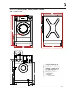
Page 13: ...26 77 467 18 39 868 34 17 858 33 78 772 30 39 770 30 31 858 33 78 13 3 Dimensions HF150 IHF150 IHF033 CHF150 CHF033 A Ventilation soap dispenser B Liquid soap connections C Hard water connections 3 4...

Page 14: ...Speed Wash 10 50 tr min RPM Distribution 85 tr min RPM Spin 250 1000 tr min RPM G factor High spin 380 Dynamic bottom load N Hz 1090 16 Motor 3 phase 4p 1470 tr min 2 2 kW 2 95 HP Drain valve 2 Water...

Page 15: ...202 7 93 1378 54 25 1350 53 15 780 30 71 680 26 77 467 18 39 15 3 Dimensions HF185 IHF185 IHF045 CHF185 CHF045 Legend metric mm inches A Ventilation soap dispenser B Liquid soap connections C Hard wat...

Page 16: ...eed Wash 10 50 tr min RPM Distribution 85 tr min RPM Spin 250 1000 tr min RPM G factor High spin 419 Dynamic bottom load N Hz 2300 15 Motor 3 phase 4p 1470 tr min 3 kW 4 02 HP Drain valve 3 Water supp...

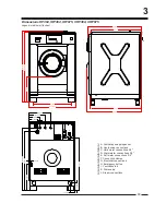
Page 17: ...946 5 37 26 1022 40 24 1002 39 45 940 37 01 3 F H 17 Dimensions HF234 IHF234 IHF055 CHF234 CHF055 Legend metric mm inches A Ventilation soap dispenser B Liquid soap connections C Hard water connection...

Page 18: ...inch Speed Wash 10 50 tr min RPM Distribution 85 tr min RPM Spin 250 1000 tr min RPM G factor High spin 475 Dynamic bottom load N Hz 2340 15 Motor 3 phase 4p 1470 tr min 4 kW 5 36 HP Drain valve 3 Wa...

Page 19: ...078 42 44 1160 45 67 1074 42 28 1158 45 59 H H F 19 3 Dimensions HF304 IHF304 IHF075 CHF304 CHF075 Legend metric mm inches A Ventilation soap dispenser B Liquid soap connections C Hard water connectio...

Page 20: ...ntirely level For easy maintenance it is recommended to keep a minimal distance of 600 mm 23 62 inch between the wall and the back of the machine If several machines are placed next to each another th...

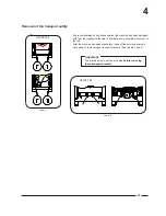
Page 21: ...d transport brackets to eliminate every possible movement of the tub After the machine has been placed level take off the service panel and back panel to remove these transport brackets See Labels 3 a...

Page 22: ...680 26 77 780 30 71 50 1 97 50 1 97 34 1 34 34 1 34 2 2 0 8 7 665 26 18 733 28 86 22 4 Mounting Bolt Hole Locations for machines HF150 IHF150 IHF033 CHF150 CHF033 Legend metric mm inches...

Page 23: ...680 26 77 780 30 71 50 1 97 50 1 97 34 1 34 34 1 34 22 0 87 765 30 12 833 32 8 23 4 Mounting Bolt Hole Locations for machines HF185 IHF185 IHF045 CHF185 CHF045 Legend metric mm inches...

Page 24: ...2 2 0 8 7 738 29 05 830 32 68 81 3 19 81 3 19 35 1 38 35 1 38 900 35 43 900 35 43 24 Mounting Bolt Hole Locations for machines HF234 IHF234 IHF055 CHF234 CHF055 4 Legend metric mm inches...

Page 25: ...4 1060 41 73 2 2 0 8 7 865 34 06 97 5 3 84 97 5 3 84 960 37 8 1040 40 94 40 1 57 40 1 57 25 Mounting Bolt Hole Locations for machines HF304 IHF304 IHF075 CHF304 CHF075 Legend metric mm inches...

Page 26: ...low capacity per minute Gallons Liters INTERNATIONAL US For the HF150 185 4 23 16 5 28 20 For the HF234 304 7 93 13 2 30 50 7 93 13 2 30 50 Water connection The diameter of the main drain should be ad...

Page 27: ...d for complete electrical overload protection This prevents damage to the motor by disconnecting all legs if one should be lost accidentally Check the data plate on the back of the washer extractor or...

Page 28: ...article 250 The ground connection must be made to a proven earth ground not to a water pipe gas pipe or another metal pipe Provide the necessary equipotential connections according to the local electr...

Page 29: ...at back of machine see chapter dimensions part F Run power cable through the cabinet knock out located directly below the cover plate Before installing obtain and install a cord grip to hold the cabl...

Page 30: ...ntified as the neutral wire to the bottom terminal of the auxiliary contactor on the power contactor switch marked N 200 240 volts 1 Phase 2 wire PE 60 Hertz called 1 phase 60 Hz X voltage With supply...

Page 31: ...2 8 50 63 10 6 X 200 240 50 60 1 3 2 3 PE 12 15 16 14 2 5 N A N A N A N A Alternative Electric Heat Options N 440 480 50 60 3 3 PE 6x2 kW 20 2 25 20 14 2 5 P 380 415 50 60 3 3 N PE 23 2 30 25 14 2 5 Q...

Page 32: ...2 8 50 63 10 6 X 200 240 50 60 1 3 2 3 PE 12 15 16 14 2 5 N A N A N A N A Alternative Electric Heat Options N 440 480 50 60 3 3 PE 6x2 kW 20 2 25 20 14 2 5 P 380 415 50 60 3 3 N PE 23 2 30 25 14 2 5 Q...

Page 33: ...3 50 63 10 6 X 200 240 50 60 1 3 2 3 PE 16 20 20 14 2 5 N A N A N A N A Alternative Electric Heat Options N 440 480 50 60 3 3 PE 6x2 kW 20 4 25 20 14 2 5 P 380 415 50 60 3 3 N PE 23 4 30 25 14 2 5 Q...

Page 34: ...US US NON US N 440 480 50 60 3 3 PE 5 2 15 16 12 4 0 6x3 kW 29 8 40 32 12 4 P 380 415 50 60 3 3 N PE 5 2 15 16 12 4 0 34 2 40 40 12 4 Q 200 240 50 60 3 3 PE 15 20 20 12 4 0 53 3 50 63 10 6 X 200 240 5...

Page 35: ...Check at regular intervals for chemical leaks CAUTION Drill out plugs and nipples before making supply hose connection Failure to do so can cause buildup of pressure and risk a tubing rupture Electric...

Page 36: ...e transformed to other values to drive other type soap pumps Example pumps 24V See Label 8 Also pumps with different operating tension can be combined Example 5 pumps 220V and 1 pump 24V See Label 9 W...

Page 37: ...be connected The right connectors form a potential free output contact as a result of which the operating panel detects when the machine is activated or not The left connectors receive the signal by...

Page 38: ...L Steam inlet connection inch Number of steam inlets Recommended pressure bar Recommended pressure psi Maximum pressure bar Maximum pressure psi For the HF150 IHF150 IHF033 CHF150 CHF033 3 8 1 2 0 5 5...

Page 39: ...0901 12kw 3x4kw See Label 15 LC1D0901 12kw 3x2kw 3x2kw See Label 15 See Label 15 LC1D1810 LC1D1810 See Label 16 LC1D1810 15kw 3x2kw 3x3kw See Label 15 See Label 15 LC1D1810 LC1D1810 See Label 16 LC1D1...

Page 40: ...skips the final spin check whether the probe of the out of balance switch is still in the appropriate position that is horizontally centered and vertically 1 3 from the bottom inside the window When...

Page 41: ...of the belt span see figure Annual maintenance Belt tension Belt tension testing table Model Belt Frequency Hz Tension force N Deflection mm Deflection force MIN MAX MIN MAX at MIN tension at MAX tens...

Page 42: ...Information Nameplate Nameplate Location The nameplate is located at the rear of the machine Always provide the machine s serial number and model number when ordering parts or when seeking technical a...

Page 43: ...cement Parts If literature or replacement parts are required contact the source from which the machine was purchased or contact the phone numbers or websites shown on the nameplate Position of the Ser...

Page 44: ...tion Installed by Serial number Operation voltage and frequency Distributor Name Address Tel Alliance Laundry Systems Shephard Street PO BOX 990 Ripon WI 54971 0990 United States Tel 001 920 748 3121...

Page 45: ......

Page 46: ......

Reviews: