background image

Installing the Washer

11

685980

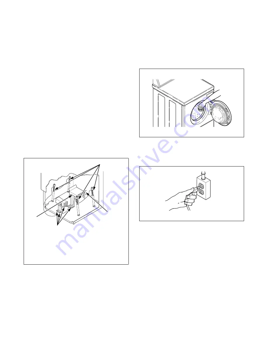
Step 5: Remove the Shock 
Sleeves and Shipping Brace

Remove front access panel by removing the two 
screws.

Remove 9/16" bolts and washers from shipping brace 
with wrench and remove brace. Remove shock sleeves 
by pulling on the yellow rope. 

Remove label from front side of front access panel and 
place on back side of front access panel.

NOTE: The shipping brace, bolts, washers, and 
shock sleeves should be saved and MUST be 
reinstalled whenever the washer is moved more 
than 4 feet. Do not lift or transport washer from 
front or without shipping materials installed. Refer 
to 

Moving Washer to a New Location

 section for 

instructions.

Store the shipping materials in the bag provided in the 
accessories bag. Save materials for use whenever the 
washer is moved.

Reinstall front access panel.

Step 6: Wipe Out Inside of 
Wash Drum

Before using washer for the first time, use an all-
purpose cleaner, or a detergent and water solution, and 
a damp cloth to remove shipping dust from inside 
washer drum.

Step 7: Plug In the Washer

Refer to section on 

Electrical Requirements

 and plug 

the washer in.

Step 8: Check Installation

Refer to 

Installer Check

 on the back cover of this 

manual and make sure that washer is installed 
correctly.

H336I

1

Shock Sleeves

2

Motor Mount

3

Bolts and Washers

4

Hooked End of Shipping Brace

1

2

3

4

H337I

H008I

H337I

D254I

Summary of Contents for H011C

Page 1: ...tion Washers H011C NOTA El manual en espa olaparecedespu s del manual en ingl s Part No 685980R3 March 2000 Keep These Instructions for Future Reference If this machine changes ownership this manual m...

Page 2: ......

Page 3: ...1 Position Washer Near Installation Area 7 Step 2 Connect Water Inlet Hoses 7 Step 3 Connect Drain Hose to Drain Receptacle 8 Standpipe Installation 8 Sink Installation 9 In the Wall Installation 9 L...

Page 4: ...rts are required contact the source from where you purchased your washer or contact Alliance Laundry Systems Shepard Street P O Box 990 Ripon WI 54971 0990 Phone 920 748 3950 for the name and address...

Page 5: ...3 685980 Roughing In Dimensions H327I H327I 28 71 1 cm 2 5 1 cm 17 5 44 8 cm 36 6 93 cm 14 9 37 9 cm 43 109 2 cm 31 1 79 cm 29 6 75 1 cm 26 9 68 3 cm...

Page 6: ...685980 4 Notes...

Page 7: ...138 to 827 kPa For more detailed information refer to section on Water Supply Requirements Accessories Bag An accessories bag has been shipped inside your washer It includes Two inlet hoses with washe...

Page 8: ...685980 6 Notes...

Page 9: ...reens in the water mixing valve NOTE When installing in newly constructed or renovated building it is very important to flush the lines since build up may have occurred during construction IMPORTANT T...

Page 10: ...rly install the drain hose IMPORTANT Drain receptacle must be capable of handling a minimum of 1 1 4 inch 32 cm outside diameter drain hose Standpipe Installation Place the drain hose into the standpi...

Page 11: ...drain hose MUST be secured to one of the inlet hoses using the beaded tie down strap from accessories bag NOTE End of drain hose must not be below 24 Laundry Tub Installation For this type of install...

Page 12: ...washer across floor if the leveling legs have been extended as legs and base could become damaged NOTE Use of the dispenser drawer or washer door as a handle in the transportation of the washer may ca...

Page 13: ...installed Refer to Moving Washer to a New Location section for instructions Store the shipping materials in the bag provided in the accessories bag Save materials for use whenever the washer is moved...

Page 14: ...685980 12 Notes...

Page 15: ...ews Place the shock sleeves on all four shock absorbers Refer to illustration Insert hooked end of shipping brace into the open slot of the motor mount Attach with bolts and washers Refer to illustrat...

Page 16: ...685980 14 Notes...

Page 17: ...oltage reading is measured other than that illustrated the qualified electrician should correct the problem D009I To reduce the risk of fire electric shock or personal injury all wiring and grounding...

Page 18: ...685980 16 Notes...

Page 19: ...t Hose 10 foot 3 05 m Water Pressure Pressure must be a minimum of 20 to a maximum of 120 pounds per square inch 138 to 827 kPa static pressure measured at the faucet NOTE Water pressure under 20 poun...

Page 20: ...685980 18 Notes...

Page 21: ...adoras con la modalidad de agitaci n H011C Pieza No 685980R3 Marzo 2000 Guarde estas instrucciones para referencia en el futuro Si la lavadora cambia de due o aseg rese de que vaya acompa ada de estas...

Page 22: ......

Page 23: ...e suministro de agua 27 Paso 3 Conexi n de la manguera de desag e al recept culo de desag e 28 Instalaci n del tubo vertical de desag e 28 Instalaci n a un lavamanos 28 Instalaci n en la pared 29 Inst...

Page 24: ...esitan piezas de repuesto comun quese con el vendedor o con Alliance Laundry Systems Shepard Street P O Box 990 Ripon WI 54971 0990 Telefono 920 748 3950 para obtener el nombre y la direcci n del dist...

Page 25: ...23 685980 SP Dimensiones aproximadas H327I H327I 71 1 cm 28 plg 5 1 cm 2 plg 44 8 cm 17 5 plg 93 cm 36 6 plg 37 9 cm 14 9 plg 109 2 cm 43 plg 79 cm 31 1 plg 75 1 cm 29 6 plg 68 3 cm 26 9 plg...

Page 26: ...685980 SP 24 Notas...

Page 27: ...n de Requisitos de suministro de agua Bolsa de accesorios Se ha enviado una bolsa de accesorios dentro de la lavadora que contiene lo siguiente Dos mangueras de suministro con arandelas Rem tase al pa...

Page 28: ...685980 SP 26 Notas...

Page 29: ...la lavadora en una vivienda reci n construida o remodelada es muy importante que limpie las tuber as dejando que el agua fluya ya que pudo haberse acumulado material en las mismas durante la construc...

Page 30: ...lada de la bolsa de accesorios col quela alrededor del tubo vertical de desag e y la manguera de desag e y apriete la correa para sujetar la manguera al tubo vertical de desag e As se evita que se sal...

Page 31: ...uedar a una altura meno que 61 cm 24 plg Instalaci n a una batea En este tipo de instalaci n la manguera de desag e DEBER asegurarse a la batea fija para evitar que la manguera se salga cuando se est...

Page 32: ...ci n al funcionar NOTA NO deslice la lavadora sobre el piso con las patas niveladoras extendidas ya que podr an resultar da adas NOTA El uso de la gaveta del surtidor o de la compuerta de la lavadora...

Page 33: ...e encuentran en la secci n Desplazamiento de la unidad a un nuevo sitio Guarde los materiales de transporte en la bolsa provista dentro de la bolsa de accesorios Conserve los materiales para usarlos c...

Page 34: ...685980 SP 32 Notas...

Page 35: ...uitos de amortiguador sobre los cuatro amortiguadores Vea la ilustraci n Inserte el lado en forma de gancho del tirante sujetador de embarque dentro de la ranura del montaje del motor Asegure con pern...

Page 36: ...685980 SP 34 Notas...

Page 37: ...traci n el electricista debe solucionar el problema D009I Para reducir el riesgo de incendio descarga el ctrica o lesiones personales todo el cableado y las conexiones a tierra DEBER N cumplir con las...

Page 38: ...685980 SP 36 Notas...

Page 39: ...icional si las mangueras que vienen con la lavadora no son lo suficientemente largas para la instalaci n Pida sus mangueras de la manera siguiente Manguera de suministro N 20617 2 44 m 8 pies Manguera...

Page 40: ...ire si entra aire en los tubos y los mismos emiten un golpeteo cuando cesa el suministro de agua Los tubos ascendentes son m s eficaces cuando se instalan lo m s cerca posible de los grifos de suminis...

Page 41: ...39 685980 SP...

Page 42: ...al recept culo de desag e Position Washer Near Installation Area Coloque la lavadora cerca del rea de instalaci n CHECK REALIZADO CHECK REALIZADO CHECK REALIZADO CHECK REALIZADO D772I H330I Position...

Reviews: