background image

164

800170

Section 5 Service Procedures

© Copyright, Alliance Laundry Systems LLC – DO NOT COPY or TRANSMIT

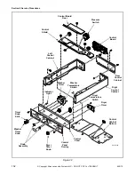
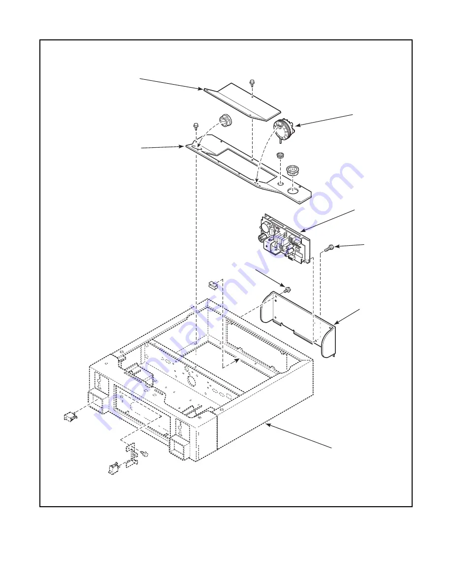
Figure 30

H062PE3A

Control

Shield

Service

Door

Pressure

Switch

Screw

Screw

Rear

Access

Panel

Control

Cabinet

Wrapper

Motor

Control

Board

Summary of Contents for HTE517xE2802

Page 1: ...www alliancelaundry com Part No 800170R3 January 2017 H010C Co mm erc ial Wa she r Dry er WA SH ER DR YE R Service Commercial Stacked Washer Dryer Refer to Page 8 for Model Numbers...

Page 2: ......

Page 3: ...uence 44 17 Shut Down Sequence 46 Troubleshooting MDC Models Washer Control 49 18 Error Code Listing 49 19 Coins Ignored When Entered 50 20 No Visible Display on Control 52 21 Washer Will Not Start No...

Page 4: ...abinet Check Wall Receptacle Polarity Gas Dryer Models Only 144 77 Ground Wire From Terminal Block To Rear Bulkhead and From Rear Bulkhead To Control Cabinet Electric Dryer Models Only 145 78 Washer G...

Page 5: ...Leveling Legs 215 133 Washer Loading Door 216 134 Washer Motor Belt Tension 217 135 Washer Door Catch 218 136 Burner Flame Gas Models 219 137 Cleaning Non Electronic Coin Drop 220 138 Cleaning Electr...

Page 6: ...4 800170 Copyright Alliance Laundry Systems LLC DO NOT COPY or TRANSMIT Notes...

Page 7: ...tructions IMPORTANT The word IMPORTANT is used to inform the reader of specific procedures where minor machine damage will occur if the procedure is not followed NOTE The word NOTE is used to communic...

Page 8: ...recommends contacting an authorized technician and using authorized factory parts To reduce the risk of electric shock fire explosion serious injury or death Disconnect electric power to the washer d...

Page 9: ...urchased or contact Alliance Laundry Systems at 920 748 3950 for the name and address of the nearest authorized parts distributor For technical assistance call 920 748 3121 Nameplate Location When cal...

Page 10: ...ric HTEY17 H X X Electric HTEY17 H2802 X X Electric HTEZ17 H X X Electric HTEZ17 H2802 X X Electric HTG519 E0902 X X Gas HTG519 H0902 X X Gas HTGB19 J0902 X X Gas HTGF19 J0902 X X Gas HTGT19 H X X Gas...

Page 11: ...STG519 E X X Gas STGA19 H X X Gas STGA19 J X X Gas STGB19 H X X Gas STGB19 J X X Gas STGC19 J X X Gas STGD19 H X X Gas STGF19 J X X Gas STGT19 H X X Gas STGY19 H X X Gas STGZ19 H X X Gas Add Letter To...

Page 12: ...How Your Washer Works Commercial Washer Dryer WASHER DRYER H159SE3A Coin Drop Motor Control Board Located inside control cabinet Pressure Switch Located inside control cabinet Mixing Valve Inner Bask...

Page 13: ...se cycles have been completed the washer goes into a final high spin cycle to extract as much water as possible from the clothing to prepare them for the dryer The spin speeds and duration of this fin...

Page 14: ...air in through louvers at the rear of the dryer and over the heat source burner flame for gas and heating element for electric The heated air moves through the heater duct and into the cylinder where...

Page 15: ...ING Section 3 Troubleshooting 1 TROUBLESHOOTING COIN DROP a Non Electronic Coin Drops When coin is placed into coin slot the coin should roll down drop and be heard dropping into coin vault If coin do...

Page 16: ...Yes SWD1714S Is proper electrical power supplied to coin drop Incorrect electrical connection may prevent coins from registering in coin drop Is coin drop clean Residue or lint build up may prevent c...

Page 17: ...g instructions Remove Coin Drop From Machine 1 Disconnect electrical power to machine and drop 2 Remove coin drop from machine Test Tension Spring 1 Push coin return button to open and close coin drop...

Page 18: ...ckwise 40 to 60 degrees until it is free from right tabs Refer to Figure 6 7 Use screwdriver to remove spring from center tab Refer to Figure 6 8 Lift spring with attached clip off drop 9 Remove clip...

Page 19: ...rt the washer dryer with any guards panels removed Whenever ground wires are removed during servicing these ground wires must be reconnected to ensure that the washer dryer is properly grounded W014R1...

Page 20: ...18 800170 Section 3 Troubleshooting Copyright Alliance Laundry Systems LLC DO NOT COPY or TRANSMIT Notes...

Page 21: ...h b To test the electrical circuit disconnect electrical power to the washer c Remove the H3 connector from the motor control board d Use an Ohm meter and check the black white to violet white wires C...

Page 22: ...hooting Washer Copyright Alliance Laundry Systems LLC DO NOT COPY or TRANSMIT Figure 10 H006BE3A Out Of Balance Switch Ballast Weight 1 1 2 Inches Left Front Shock Tape Washer Base Wire Harness 8 inch...

Page 23: ...brush Refer to appropriate service procedure below SERVICE PROCEDURE STUCK BRUSHES a Remove motor from washer Refer to Paragraph 100 b Using a flashlight view brushes through holes in motor end shield...

Page 24: ...re hangs up on brush holder BRAIDED COPPER WIRE Must be positioned away from this brush holder Braided wire should loop up and away from bottom of brush holder Refer to Figure 12 Braided Copper Wire S...

Page 25: ...o ensure that the washer dryer is properly grounded W014R1 WARNING Copyright Alliance Laundry Systems LLC DO NOT COPY or TRANSMIT SERVICE PROCEDURE WORN BRUSHES a Remove motor from washer Refer to Par...

Page 26: ...W014R1 WARNING Copyright Alliance Laundry Systems LLC DO NOT COPY or TRANSMIT SERVICE PROCEDURE CLOGGED BRUSHES a Remove motor from washer Refer to Paragraph 100 b Using a flashlight view brushes thro...

Page 27: ...on causes transformer unplugged or defective wiring to motor control incorrect This is a fatal error c E FL Fill error This error occurs if the pressure switch fails to open in 30 minutes in any fill...

Page 28: ...Is there any acknowledgement of any kind from electronic control Communication sequence checks out Check the following Low battery on Micro wand Is IR on control covered or blocked Is IR cap properly...

Page 29: ...rompting for a vend No Yes Yes No Yes Yes Does the display coin counter increment properly Is connection at H2 firmly seated in its receptacle on control Is 3 pin connector plug firmly seated in its r...

Page 30: ...Electronic control has no LED or VFD functioning on control board Plug electronic control washer into electrical outlet Disconnect power and check for a broken loose or incorrect wiring from electric...

Page 31: ...CHANICAL THERMAL DOOR LOCK ACTUATOR PUMP HOT H COLD H3 H1 FS2 H2 FIELD TACH ROTOR C SV PRESSURE SWITCH 1 3 5 4 D1 D2 D3 6 2 A2 A1 DV 3 1 2 4 5 7 6 SOFTENER Control Logic Circuit Low Voltage MOTOR DC P...

Page 32: ...there voltage at blu blk input wire to door switch on lock assembly No 4 AC 5 AC Is there voltage at H5 1 to FS 2 on electronic control board Is there voltage at H3 1 to FS 2 on electronic control boa...

Page 33: ...MECHANICAL THERMAL DOOR LOCK ACTUATOR PUMP HOT H COLD H3 H1 FS2 H2 FIELD TACH ROTOR C SV PRESSURE SWITCH 1 3 5 4 D1 D2 D3 6 2 A2 A1 DV 3 1 2 4 5 7 6 SOFTENER Control Logic Circuit Low Voltage MOTOR D...

Page 34: ...e Laundry Systems LLC DO NOT COPY or TRANSMIT 10 WASHER WILL NOT START ELECTRONIC CONTROL ANALYSIS Washer will not start Door is locked Refer to Washer will not fill No Yes 1 AC Is there voltage at H3...

Page 35: ...HANICAL THERMAL DOOR LOCK ACTUATOR PUMP HOT H COLD H3 H1 FS2 H2 FIELD TACH ROTOR C SV PRESSURE SWITCH 1 3 5 4 D1 D2 D3 6 2 A2 A1 DV 3 1 2 4 5 7 6 SOFTENER Control Logic Circuit Low Voltage MOTOR DC PO...

Page 36: ...3 AC No Still no voltage Yes No Is there voltage at input side of pressure switch to FS 2 on motor control Correct wiring at pressure switch Correct wiring between electronic control and pressure swit...

Page 37: ...IZED MECHANICAL THERMAL DOOR LOCK ACTUATOR PUMP HOT H COLD H3 H1 FS2 H2 FIELD TACH ROTOR C SV PRESSURE SWITCH 1 3 5 4 D1 D2 D3 6 2 A2 A1 DV 3 1 2 4 5 7 6 SOFTENER Control Logic Circuit Low Voltage MOT...

Page 38: ...ge inoperative pressure switch Note Go through the following tests if water is at least half way up the door glass Yes Yes 1 AC 2 AC Yes No Washer still fills No Is there voltage on terminal 24 on pre...

Page 39: ...ZED MECHANICAL THERMAL DOOR LOCK ACTUATOR PUMP HOT H COLD H3 H1 FS2 H2 FIELD TACH ROTOR C SV PRESSURE SWITCH 1 3 5 4 D1 D2 D3 6 2 A2 A1 DV 3 1 2 4 5 7 6 SOFTENER Control Logic Circuit Low Voltage MOTO...

Page 40: ...electronic control board Check for a kink or blockage in drain hose Change inoperative electronic control board Note Make sure washer cycle is in drain spin Yes 1 AC 2 AC No Yes Still will not pump N...

Page 41: ...GIZED MECHANICAL THERMAL DOOR LOCK ACTUATOR PUMP HOT H COLD H3 H1 FS2 H2 FIELD TACH ROTOR C SV PRESSURE SWITCH 1 3 5 4 D1 D2 D3 6 2 A2 A1 DV 3 1 2 4 5 7 6 SOFTENER Control Logic Circuit Low Voltage MO...

Page 42: ...s between electronic and motor control boards Connect loose harness s and retry washer cycle Yes 1 AC Lower than 20 volts AC 20 volts AC E SP still continues No Are all the control wiring harnesses co...

Page 43: ...GIZED MECHANICAL THERMAL DOOR LOCK ACTUATOR PUMP HOT H COLD H3 H1 FS2 H2 FIELD TACH ROTOR C SV PRESSURE SWITCH 1 3 5 4 D1 D2 D3 6 2 A2 A1 DV 3 1 2 4 5 7 6 SOFTENER Control Logic Circuit Low Voltage MO...

Page 44: ...ansformer Using an Ohmmeter check red black wire from transformer to H1 7 on motor control board for broken wire poor connection If none found replace transformer 2 Is there continuity Check continuit...

Page 45: ...HEN DE ENERGIZED MECHANICAL THERMAL DOOR LOCK ACTUATOR PUMP HOT H COLD H3 H1 FS2 H2 FIELD TACH ROTOR C SV PRESSURE SWITCH 1 3 5 4 D1 D2 D3 6 2 A2 A1 DV 3 1 2 4 5 7 6 SOFTENER Control Logic Circuit Low...

Page 46: ...d price has been satisfied c The door lock actuator is energized from H5 1 terminal on electronic control board d The door lock switch is closed e The K4 relay is closed on electronic control board f...

Page 47: ...CHANICAL THERMAL DOOR LOCK ACTUATOR PUMP HOT H COLD H3 H1 FS2 H2 FIELD TACH ROTOR C SV PRESSURE SWITCH 1 3 5 4 D1 D2 D3 6 2 A2 A1 DV 3 1 2 4 5 7 6 SOFTENER Control Logic Circuit Low Voltage MOTOR DC P...

Page 48: ...NOT COPY or TRANSMIT 17 SHUT DOWN SEQUENCE a Towards end of cycle 01 is on display The door lock actuator is powered down and K2 relay on electronic control is opened b The door lock switch is opened...

Page 49: ...ZED MECHANICAL THERMAL DOOR LOCK ACTUATOR PUMP HOT H COLD H3 H1 FS2 H2 FIELD TACH ROTOR C SV PRESSURE SWITCH 1 3 5 4 D1 D2 D3 6 2 A2 A1 DV 3 1 2 4 5 7 6 SOFTENER Control Logic Circuit Low Voltage MOTO...

Page 50: ...48 800170 Section 3 Troubleshooting EDC Models Washer Control Copyright Alliance Laundry Systems LLC DO NOT COPY or TRANSMIT Notes...

Page 51: ...e with the motor control The master control will try to reset the motor control by powering it down It will try resetting three times before setting the error code Common causes include defective or u...

Page 52: ...H7 connector properly seated on the control board No Properly reseat connection and conduct diagnostic test again Yes From the coin drop is the 3 pin connector properly plugged in Yes No Properly res...

Page 53: ...800170 51 Section 3 Troubleshooting MDC Models Washer Control Copyright Alliance Laundry Systems LLC DO NOT COPY or TRANSMIT Notes...

Page 54: ...er cord plugged in Plug unit into an outlet and check for proper supply voltage No Yes 1 No Is there 24 Volt AC at the output side of the transformer Is there 120 AC to the primary of the transformer...

Page 55: ...800170 53 Section 3 Troubleshooting MDC Models Washer Control Copyright Alliance Laundry Systems LLC DO NOT COPY or TRANSMIT NO VISIBLE DISPLAY ON CONTROL 801182 1 2 3...

Page 56: ...Yes Is there 120 Volt AC across H4 4 to H6 5 on the control board 4 Replace the Door Lock Assembly No Is there 120 Volt AC across H6 1 and H6 5 on the control board No 5 Replace the Control Board No...

Page 57: ...800170 55 Section 3 Troubleshooting MDC Models Washer Control Copyright Alliance Laundry Systems LLC DO NOT COPY or TRANSMIT WASHER WILL NOT START NO DOOR LOCK 801182 5 2 3 1 4...

Page 58: ...ance Laundry Systems LLC DO NOT COPY or TRANSMIT 22 WASHER WILL NOT START CONTROL ANALYSIS Washer Will Not Start Control Analysis Is there 120 Volt AC across H6 6 to H6 5 on the control board 1 Yes No...

Page 59: ...800170 57 Section 3 Troubleshooting MDC Models Washer Control Copyright Alliance Laundry Systems LLC DO NOT COPY or TRANSMIT WASHER WILL NOT START CONTROL ANALYSIS 801182 1...

Page 60: ...control board Correct wiring between pressure switch and control board No Is there 120 Volt AC from the input side of the mixing valves to FS2 on the motor control board Yes 1 2 3 Yes Check for crack...

Page 61: ...800170 59 Section 3 Troubleshooting MDC Models Washer Control Copyright Alliance Laundry Systems LLC DO NOT COPY or TRANSMIT WASHER WILL NOT FILL 801182 1 3 2...

Page 62: ...FLOWS Washer Overflows Is there voltage to the over level terminal on pressure switch to FS2 Yes No Replace inoperative pressure switch Is there voltage across the coil of either the hot or cold water...

Page 63: ...800170 61 Section 3 Troubleshooting MDC Models Washer Control Copyright Alliance Laundry Systems LLC DO NOT COPY or TRANSMIT WASHER OVERFLOWS 801182 1 2...

Page 64: ...Does Not Operate Is there voltage across the wht blk and the white wire going to the motor Is there voltage across terminals H6 2 and H6 5 NOTE Check at beginning of spin drain portion of cycle If th...

Page 65: ...800170 63 Section 3 Troubleshooting MDC Models Washer Control Copyright Alliance Laundry Systems LLC DO NOT COPY or TRANSMIT PUMP DOES NOT OPERATE 801182 2 1...

Page 66: ...mer Using an Ohmmeter check red black wire from transformer to H1 7 on motor control board for broken wire poor connection If none found replace transformer TRANSFORMER 2 Is there continuity Check con...

Page 67: ...800170 65 Section 3 Troubleshooting MDC Models Washer Control Copyright Alliance Laundry Systems LLC DO NOT COPY or TRANSMIT DOOR LOCKED MOTOR DOES NOT RUN E df on display 801182 2 1 4 3...

Page 68: ...66 800170 Section 3 Troubleshooting MDC Models Washer Control Copyright Alliance Laundry Systems LLC DO NOT COPY or TRANSMIT Notes...

Page 69: ...ode Incorrect machine type Before downloading ensure data is for current machine type EI 04 Expecting Upload Request Communication failure Re aim Micro Wand and try again EI 05 Invalid or Out of Range...

Page 70: ...te Failure Faulty card reader Replace card reader EC 28 Diagnostic Test Card Read Failure Faulty card reader Replace card reader EC 29 Diagnostic Test Memory Test Failure Faulty card reader Replace ca...

Page 71: ...er cycle completion Open and reclose door E do Door Opened During A Running Cycle Control detects door open and door locked inputs high Caused by pulling on door while locked or about to lock Correct...

Page 72: ...er and try again No Yes Does the Microwand prompt Control Mismatch error Is there any control response Yes Check the following Microwand battery voltage Blockage of IR window on control Attachment of...

Page 73: ...Is H7 connector properly seated on the control board No Properly reseat connection and conduct diagnostic test again Yes From the coin drop is the 3 pin connector properly plugged in Yes No Properly...

Page 74: ...power cord plugged in Plug unit into an outlet and check for proper supply voltage No Yes 1 No Is there 24 Volt AC at the output side of the transformer Is there 120 AC to the primary of the transform...

Page 75: ...1 2 1 8 9 COMM SD SW CV SW CD1 SVDC CD1 CD1 COMM CD2 SVDC CD2 CD2 COMM PE COMM COMM SVDC 24VDC CRP NBP SVDC COMM COMM NRFA NAG VUR RXD TXD 24VDC SVDC 1 3 5 8 4 1 7 3 6 9 2 K1 K2 H2 VCC SOMI CLK SIMO G...

Page 76: ...Yes Yes Is there 120 Volt AC across H4 4 to H6 5 on the control board 4 Replace the Door Lock Assembly No Is there 120 Volt AC across H6 1 and H6 5 on the control board No 5 Replace the Control Board...

Page 77: ...11 2 1 8 9 COMM SD SW CV SW CD1 SVDC CD1 CD1 COMM CD2 SVDC CD2 CD2 COMM PE COMM COMM SVDC 24VDC CRP NBP SVDC COMM COMM NRFA NAG VUR RXD TXD 24VDC SVDC 1 3 5 8 4 1 7 3 6 9 2 K1 K2 H2 VCC SOMI CLK SIMO...

Page 78: ...lliance Laundry Systems LLC DO NOT COPY or TRANSMIT 32 WASHER WILL NOT START CONTROL ANALYSIS Washer Will Not Start Control Analysis Is there 120 Volt AC across H6 6 to H6 5 on the control board 1 Yes...

Page 79: ...800170 77 Section 3 Troubleshooting NetMaster Models Washer Control Copyright Alliance Laundry Systems LLC DO NOT COPY or TRANSMIT WASHER WILL NOT START CONTROL ANALYSIS...

Page 80: ...tor control board Correct wiring between pressure switch and control board No Is there 120 Volt AC from the input side of the mixing valves to FS2 on the motor control board Yes 1 2 3 Yes Check for cr...

Page 81: ...1 8 9 COMM SD SW CV SW CD1 SVDC CD1 CD1 COMM CD2 SVDC CD2 CD2 COMM PE COMM COMM SVDC 24VDC CRP NBP SVDC COMM COMM NRFA NAG VUR RXD TXD 24VDC SVDC 1 3 5 8 4 1 7 3 6 9 2 K1 K2 H2 VCC SOMI CLK SIMO GND 3...

Page 82: ...VERFLOWS Washer Overflows Is there voltage to the over level terminal on pressure switch to FS2 Yes No Replace inoperative pressure switch Is there voltage across the coil of either the hot or cold wa...

Page 83: ...8 9 COMM SD SW CV SW CD1 SVDC CD1 CD1 COMM CD2 SVDC CD2 CD2 COMM PE COMM COMM SVDC 24VDC CRP NBP SVDC COMM COMM NRFA NAG VUR RXD TXD 24VDC SVDC 1 3 5 8 4 1 7 3 6 9 2 K1 K2 H2 VCC SOMI CLK SIMO GND 3...

Page 84: ...ump Does Not Operate Is there voltage across the wht blk and the white wire going to the motor Is there voltage across terminals H6 2 and H6 5 NOTE Check at beginning of spin drain portion of cycle If...

Page 85: ...1 8 9 COMM SD SW CV SW CD1 SVDC CD1 CD1 COMM CD2 SVDC CD2 CD2 COMM PE COMM COMM SVDC 24VDC CRP NBP SVDC COMM COMM NRFA NAG VUR RXD TXD 24VDC SVDC 1 3 5 8 4 1 7 3 6 9 2 K1 K2 H2 VCC SOMI CLK SIMO GND...

Page 86: ...84 800170 Section 3 Troubleshooting NetMaster Models Washer Control Copyright Alliance Laundry Systems LLC DO NOT COPY or TRANSMIT Notes...

Page 87: ...oading door not closed Close door Inoperative door switch Test switch and replace if inoperative Timer improperly set Reset timer or try another cycle Inoperative timer Test timer and replace if inope...

Page 88: ...OTECTOR POSSIBLE CAUSE TO CORRECT Incorrect Voltage See nameplate in door well for correct voltage Refer to Installation Instructions supplied with dryer for electrical requirements Clothes load too l...

Page 89: ...d rear bulkheads for warping Check cylinder rollers for binding Check cylinder seals and glides for wear or damage Broken weak or disconnected idler lever spring Replace or reconnect spring Refer to F...

Page 90: ...at Test thermostat and replace if inoperative Inoperative drive motor switch Test switch and replace if inoperative Electric Models Inoperative heater assembly Test heater assembly and replace if cold...

Page 91: ...structions supplied with dryer for exhaust requirements Burner heat not holding sensor contacts open Replace sensor or correct gas supply problem Insufficient gas supply Check gas supply and pressure...

Page 92: ...jumper wire across thermostat terminals If heater element heats or burner ignites when jumper wire is connected refer to Paragraph 45 Gas models Sensor contact closing Replace sensor Paragraph 117 ste...

Page 93: ...heater assembly and check for short POSSIBLE CAUSE TO CORRECT Heater assembly does not heat or burner does not ignite Refer to Paragraph 40 Too much water in articles being dried Remove excess water...

Page 94: ...ER POSSIBLE CAUSE TO CORRECT Improper or inadequate exhaust system Refer to Installation Instructions supplied with dryer for exhaust requirements Clothes are removed from dryer before cycle has compl...

Page 95: ...between Micro wand IIIe and electronic control during communication E 05 Invalid Value Communication Invalid code downloaded from Micro wand IIIe to electronic control E 07 Inoperative Control Replac...

Page 96: ...Is there any acknowledgement of any kind from electronic control Communication sequence checks out Check the following Low battery on Micro wand Is IR on control covered or blocked Is IR cap properly...

Page 97: ...rompting for a vend No Yes Yes No Yes Yes Does the display coin counter increment properly Is connection at H2 firmly seated in its receptacle on control Is 3 pin connector plug firmly seated in its r...

Page 98: ...ntrol board Replace electronic control Open Control Panel Plug electronic unit into electrical outlet ELECTRONIC CONTROL HAS NO VISIBLE DISPLAY DRYER YES YES Disconnect power and check for broken loos...

Page 99: ...H6 2 H6 1 H4 2 FS 1 DOOR SWITCH L1 L2 N 1 COM 2 NC 3 NC H4 3 H4 6 H4 1 H4 5 RELAY K2 COIN DROP SENSOR H3 1 MAIN START TP H2 1 H2 2 H2 3 H2 5 H2 6 H2 4 SERVICE DOOR COIN VAULT TEMPERATURE REGULATING CI...

Page 100: ...ay counts Does the cycle counter advance Check wiring and connections Replace coin drop The audit coin count will not advance in the diagnostic cycle Micro wand or manual electronic control audit will...

Page 101: ...800170 99 Section 3 Troubleshooting EDC Models Dryer Control Copyright Alliance Laundry Systems LLC DO NOT COPY or TRANSMIT Notes...

Page 102: ...nostic test Dryer on temperature test if SH or OP appear do the following checks Check wiring at thermistor Replace thermistor NO Replace limit thermostat and thermal fuse YES YES Does the thermistor...

Page 103: ...H6 2 H6 1 H4 2 FS 1 DOOR SWITCH L1 L2 N 1 COM 2 NC 3 NC H4 3 H4 6 H4 1 H4 5 RELAY K2 COIN DROP SENSOR H3 1 MAIN START TP H2 1 H2 2 H2 3 H2 5 H2 6 H2 4 SERVICE DOOR COIN VAULT TEMPERATURE REGULATING CI...

Page 104: ...or switch NO NO YES YES YES Check voltage at GREY H4 1 to H4 3 Is there voltage Check voltage at BROWN H4 4 to H4 3 Is there voltage NOTE This test is based on the assumption that the start button has...

Page 105: ...ELAY K1 H6 2 H6 1 H4 2 FS 1 DOOR SWITCH L1 L2 N 1 COM 2 NC 3 NC H4 3 H4 6 H4 1 H4 5 RELAY K2 COIN DROP SENSOR H3 1 MAIN START TP H2 1 H2 2 H2 3 H2 5 H2 6 H2 4 SERVICE DOOR COIN VAULT TEMPERATURE REGUL...

Page 106: ...NO Open control voltage check GREY H4 6 to H4 3 GREY H4 1 to H4 3 This checks voltage on door switch coming into control and input to K1 motor relay Still Flashing Replace door switch YES YES Display...

Page 107: ...RELAY K1 H6 2 H6 1 H4 2 FS 1 DOOR SWITCH L1 L2 N 1 COM 2 NC 3 NC H4 3 H4 6 H4 1 H4 5 RELAY K2 COIN DROP SENSOR H3 1 MAIN START TP H2 1 H2 2 H2 3 H2 5 H2 6 H2 4 SERVICE DOOR COIN VAULT TEMPERATURE REGU...

Page 108: ...tor NO Replace inoperative limit thermostat YES YES Does the thermistor temperature check out according to the diagnostic test NO YES YES Open lower front panel and check glow bar Is the glow bar acti...

Page 109: ...H6 1 H4 2 FS 1 DOOR SWITCH L1 N 1 COM 2 NC 3 NC H4 3 H4 6 H4 1 H4 5 RELAY K2 COIN DROP SENSOR H3 1 IGNITER BOOSTER COIL MAIN START TP H2 1 H2 2 H2 3 H2 5 H2 6 H2 4 SERVICE DOOR COIN VAULT TEMPERATURE...

Page 110: ...to H4 3 Is there voltage Check voltage at BROWN H4 4 to H4 3 Is there voltage Numbers next to voltage checks correspond to the locations marked on the wiring schematic NOTE This test is based on the a...

Page 111: ...Y K1 H6 2 H6 1 H4 2 FS 1 DOOR SWITCH L1 N 1 COM 2 NC 3 NC H4 3 H4 6 H4 1 H4 5 RELAY K2 COIN DROP SENSOR H3 1 IGNITER BOOSTER COIL MAIN START TP H2 1 H2 2 H2 3 H2 5 H2 6 H2 4 SERVICE DOOR COIN VAULT TE...

Page 112: ...e Display or Coins Ignored When Entered NO Open control voltage check GREY H4 6 to H4 3 GREY H4 1 to H4 3 This checks voltage on door switch coming into control and input to K1 motor relay Still Flash...

Page 113: ...AY K1 H6 2 H6 1 H4 2 FS 1 DOOR SWITCH L1 N 1 COM 2 NC 3 NC H4 3 H4 6 H4 1 H4 5 RELAY K2 COIN DROP SENSOR H3 1 IGNITER BOOSTER COIL MAIN START TP H2 1 H2 2 H2 3 H2 5 H2 6 H2 4 SERVICE DOOR COIN VAULT T...

Page 114: ...112 800170 Section 3 Troubleshooting EDC Models Dryer Control Copyright Alliance Laundry Systems LLC DO NOT COPY or TRANSMIT Notes...

Page 115: ...ng MDC Models Dryer Control 60 ERROR CODE LISTING OP Open Thermistor Error This error code indicates a physical open in the thermistor circuit Possible causes are 1 thermistor 2 wiring between control...

Page 116: ...in connector between the coin drop and the control connected correctly Are wires exiting coin drop optical sensor cracked or broken Start coin drop diagnostic test Refer to Production Test Cycle secti...

Page 117: ...800170 115 Section 3 Troubleshooting MDC Models Dryer Control Copyright Alliance Laundry Systems LLC DO NOT COPY or TRANSMIT Notes...

Page 118: ...the control Replace the transformer Are there 24 volts AC across terminals H1 3 and H1 1 on the control Correct wiring to the primary of the transformer Make sure the machine is plugged in and power...

Page 119: ...800170 117 Section 3 Troubleshooting MDC Models Dryer Control Copyright Alliance Laundry Systems LLC DO NOT COPY or TRANSMIT NO VISIBLE DISPLAY ON CONTROL DRYER 1 2 3...

Page 120: ...o check neutral supply to control Correct wiring to door switch Check operation of the door switch Replace if necessary Is there voltage across terminals H2 1 and H2 6 Is there voltage on the N O term...

Page 121: ...800170 119 Section 3 Troubleshooting MDC Models Dryer Control Copyright Alliance Laundry Systems LLC DO NOT COPY or TRANSMIT DOOR OPEN 1 2 3...

Page 122: ...2 4 and H2 6 on the control Is there voltage across H2 1 and H2 6 on the control Replace the motor Correct the wiring to the motor Replace the electronic control Refer to door open troubleshooting NOT...

Page 123: ...800170 121 Section 3 Troubleshooting MDC Models Dryer Control Copyright Alliance Laundry Systems LLC DO NOT COPY or TRANSMIT MOTOR WILL NOT START 1 2 3...

Page 124: ...e Is there voltage on FS 1 on the control to L2 Is there voltage on FS 2 on the control board to L2 Check for proper operation of centrifugal switch on motor Does it operate properly Replace heating e...

Page 125: ...800170 123 Section 3 Troubleshooting MDC Models Dryer Control Copyright Alliance Laundry Systems LLC DO NOT COPY or TRANSMIT NO HEAT ELECTRIC 1 2 8 3 4 5 6 7...

Page 126: ...ect wiring between FS 1 and limit thermostat Check for proper air flow making sure venting is not blocked and lint screen is clean Replace limit thermostat Correct wiring between limit thermostat and...

Page 127: ...800170 125 Section 3 Troubleshooting MDC Models Dryer Control Copyright Alliance Laundry Systems LLC DO NOT COPY or TRANSMIT NO HEAT GAS 6 1 2 3 4 5...

Page 128: ...126 800170 Section 3 Troubleshooting MDC Models Dryer Control Copyright Alliance Laundry Systems LLC DO NOT COPY or TRANSMIT Notes...

Page 129: ...Range Data Incorrect machine type Before downloading ensure data is for current machine type EI 06 Invalid Data Code Incorrect machine type Before downloading ensure data is for current machine type E...

Page 130: ...Faulty card reader Replace card reader EC 29 Diagnostic Test Memory Test Failure Faulty card reader Replace card reader EC 2A Diagnostic Test Card Interface Failure Faulty card reader Replace card rea...

Page 131: ...k sensor for proper ohms reading If shorted replace sensor Err Coin Error Invalid coin pulse or inoperative coin sensor Check coin drop area and remove obstructions If error persists tampering may hav...

Page 132: ...rol firmly seated in its receptacle Is the 3 pin connector between the coin drop and the control connected correctly Are wires exiting coin drop optical sensor cracked or broken Start coin drop diagno...

Page 133: ...gain Check the following Low battery on microwand Is the IR window covered or blocked on the control If needed replace the electronic control Is the IR cup properly attached to the microwand Communica...

Page 134: ...ol Replace the transformer Are there 24 volts AC across terminals H1 3 and H1 1 on the control Correct wiring to the primary of the transformer Make sure the machine is plugged in and power is on Are...

Page 135: ...800170 133 Section 3 Troubleshooting NetMaster Models Dryer Control Copyright Alliance Laundry Systems LLC DO NOT COPY or TRANSMIT NO DISPLAY 3 2 1 DRY352S_...

Page 136: ...ntrol Correct wiring to door switch Check operation of the door switch Replace if necessary Is there voltage across terminals H2 1 and H2 6 Is there voltage on the N O terminal of the door switch to a...

Page 137: ...800170 135 Section 3 Troubleshooting NetMaster Models Dryer Control Copyright Alliance Laundry Systems LLC DO NOT COPY or TRANSMIT DOOR OPEN 4 2 1 3 DRY1816S...

Page 138: ...s H2 4 and H2 6 on the control Is there voltage across H2 1 and H2 6 on the control Replace the motor Correct the wiring to the motor Replace the electronic control Refer to door open troubleshooting...

Page 139: ...800170 137 Section 3 Troubleshooting NetMaster Models Dryer Control Copyright Alliance Laundry Systems LLC DO NOT COPY or TRANSMIT MOTOR WILL NOT START 3 1 2 DRY358S_...

Page 140: ...re voltage on FS 1 on the control to L2 Is there voltage on FS 2 on the control board to L2 Check for proper operation of centrifugal switch on motor Does it operate properly Replace heating element C...

Page 141: ...800170 139 Section 3 Troubleshooting NetMaster Models Dryer Control Copyright Alliance Laundry Systems LLC DO NOT COPY or TRANSMIT NO HEAT ELECTRIC 6 7 5 4 3 2 1 8 DRY360S_...

Page 142: ...nd H2 3 neutral on the control Correct wiring between FS 1 and limit thermostat Is there voltage across FS 2 and H2 3 neutral on the control Make sure unit is calling for heat Check operation of therm...

Page 143: ...800170 141 Section 3 Troubleshooting NetMaster Models Dryer Control Copyright Alliance Laundry Systems LLC DO NOT COPY or TRANSMIT NO HEAT GAS 6 1 2 3 4 5 DRY362S_...

Page 144: ...142 800170 Section 3 Troubleshooting NetMaster Models Dryer Control Copyright Alliance Laundry Systems LLC DO NOT COPY or TRANSMIT Notes...

Page 145: ...ever ground wires are removed during servicing these ground wires must be reconnected to ensure that the washer dryer is properly grounded W014R1 WARNING Section 4 Grounding 75 WALL RECEPTACLE POLARIT...

Page 146: ...Never start the washer dryer with any guards panels removed Whenever ground wires are removed during servicing these ground wires must be reconnected to ensure that the washer dryer is properly groun...

Page 147: ...gas shut off valve to gas dryer before servicing Never start the washer dryer with any guards panels removed Whenever ground wires are removed during servicing these ground wires must be reconnected t...

Page 148: ...ires are removed during servicing these ground wires must be reconnected to ensure that the washer dryer is properly grounded W014R1 WARNING 78 WASHER GROUND CONNECTIONS Refer to Figure 18 Ground to E...

Page 149: ...800170 147 Section 4 Grounding Copyright Alliance Laundry Systems LLC DO NOT COPY or TRANSMIT Figure 18 H004GE3A 1 2 3 5 6 7 8 9 10 11 12 4 Ground Wire From Dryer...

Page 150: ...ved Whenever ground wires are removed during servicing these ground wires must be reconnected to ensure that the washer dryer is properly grounded W014R1 WARNING 79 GROUND WIRES FROM DRYER TO CONTROL...

Page 151: ...n 5 Service Procedures IMPORTANT When reference is made to directions right or left in this manual it is from operator s position facing front of machine 80 TO REMOVE THE DRYER Refer to Figure 20 IMPO...

Page 152: ...lectronic control will be minimized Always handle electronic control by its metal edges If a wrist strap is not available touch washer while it is plugged in before handling control to dissipate any c...

Page 153: ...ure 22 Remove panel as far as wires will permit 83 CONTROLS Non Metered Models a Remove control panel Refer to Paragraph 82 b Disconnect two wires from indicator light NOTE Refer to wiring diagram whe...

Page 154: ...ryer DR YE R SWD556P Control Shield Control Shield Door Pressure Switch Control Board Right Control Cabinet Rear Control Cabinet Dryer Timer Control Cabinet Bottom Left Control Cabinet Control Panel I...

Page 155: ...NDICATOR LIGHT Metered Models Washer Door Locked a Unlock control panel Refer to Figure 21 Step 1 b Pull top of control panel away from control cabinet far enough to allow lifting control panel up and...

Page 156: ...edges remove control from foam and wrapping a Unlock control panel Refer to Figure 21 Step 1 b Pull top of control panel away from control cabinet far enough to allow lifting control panel up and off...

Page 157: ...panel away from control cabinet as far as wires permit Refer to Figure 21 Step 3 4 Support control panel press in on locking tabs and unplug harness disconnect blocks from backside of electronic cont...

Page 158: ...n of coin drop 5 Disconnect coin drop harness at disconnect block 6 Use a 3 8 inch square drive socket with number 310P4 quarter inch Ratchet Extension Tool to remove 2 locknuts holding coin drop to f...

Page 159: ...ance Laundry Systems LLC DO NOT COPY or TRANSMIT Figure 24 H162SE3A Guide Wires Coin Drop Locknut Coin Drawer Housing Control Cabinet Front Disconnect Block 3 8 Inch Square Drive 7 16 Inch Socket No 3...

Page 160: ...1 Step 2 3 Remove control panel away from control cabinet as far as wires permit Refer to Figure 21 Step 3 NOTE Carefully place protective padding around control panel assembly to keep panel assembly...

Page 161: ...ep 3 4 Disconnect card reader harness at disconnect block 5 Use a 3 8 inch square drive socket with number 310P4 1 4 inch Ratchet Extension Tool to remove screws or nuts holding card reader to control...

Page 162: ...A RD HE RE CardMate System IN SE RT CA RD HE RE CardMate System SWD1653S Card Reader Card Reader Attaching Screw Control Cabinet Wrapper Control Cabinet Front MODELS EQUIPPED WITH 39685 CARD READER MO...

Page 163: ...h Remove control panel Refer to Paragraph 81 or 82 i Working through control panel opening remove two screws holding bottom flange of control cabinet front to top flange of front panel j Remove bottom...

Page 164: ...70 Section 5 Service Procedures Copyright Alliance Laundry Systems LLC DO NOT COPY or TRANSMIT Figure 29 FLW1190B STEP 2 Pull seal out STEP 1 Pull seal up STEP 3 Pull seal down STEP 2 Pull seal out an...

Page 165: ...associated with handling of motor control board will be minimized Always handle motor control board by its metal edges If a wrist strap is not available touch washer while it is plugged in before han...

Page 166: ...Service Procedures Copyright Alliance Laundry Systems LLC DO NOT COPY or TRANSMIT Figure 30 H062PE3A Control Shield Service Door Pressure Switch Screw Screw Rear Access Panel Control Cabinet Wrapper...

Page 167: ...control cabinet Refer to Figure 30 b Tilt access panel back far enough to disengage bottom of access panel from opening in control cabinet c Disconnect wires from pressure switch at disconnect block...

Page 168: ...rom bottom edge of lower access panel Refer to Figure 31 b Gently lower the access panel to disengage panel locators from bottom edge of front panel IMPORTANT There will always be some water that will...

Page 169: ...r and remove two screws holding rear access panel to rear of control cabinet Refer to Figure 30 b Tilt access panel back far enough to disengage bottom of access panel from opening in control cabinet...

Page 170: ...sure that the washer dryer is properly grounded W014R1 WARNING 95 MIXING VALVE NOTE Mixing valve is located on upper back right corner of rear panel Refer to Figure 34 a Go to rear of washer and remov...

Page 171: ...ervice Procedures Copyright Alliance Laundry Systems LLC DO NOT COPY or TRANSMIT Figure 34 H165SE3A Mixing Valve To Dispenser Hose Hose Clamp Inlet Hose Screws Mixing Valve Plate Wire Harness Disconne...

Page 172: ...T Figure 35 Figure 36 B L E A C H S O F T E N E R M AX M AX Co mm erc ial Was he r Dr ye r WAS HE R DR YE R H166SE3A Door Switch Door Switch Wires Door Latch Switch Wire Harness and Wires Door Latch S...

Page 173: ...d W014R1 WARNING 96 WASHER LOADING DOOR a Open loading door b Remove door bezel to gain access to nuts Refer to Figure 37 c The loading door can be adjusted up or down somewhat by loosening screws hol...

Page 174: ...front to top flange of washer front panel Refer to Figure 26 h While supporting lower access panel remove two screws from bottom edge of lower access panel Refer to Figure 31 i Gently lower access pan...

Page 175: ...Y or TRANSMIT Figure 38 Co mm ercia l Was he r Dr ye r WAS HE R DR YE R H169SE3A Wire Harness Clip Door Switch Notch Door Latch Switch Large Clamp When installing door seal align connecting hose in ve...

Page 176: ...far enough to allow removal of wires from switch terminals IMPORTANT Refer to wiring diagram when rewiring switch 99 WASHER DOOR LATCH SWITCH a Open loading door b Carefully remove wire clamp ring fr...

Page 177: ...motor e Remove screw holding ground wire to motor frame Refer to Figure 40 f Disconnect motor harness connector from motor g While supporting the motor grasp the metal rod with a locking pliers and r...

Page 178: ...Copyright Alliance Laundry Systems LLC DO NOT COPY or TRANSMIT Figure 40 Co mm erc ial Was he r Dr ye r WAS HE R DR YE R H171SE3A Adjusting Bolt Pivot Bolt Ground Wire Wire Harness Metal Rod Pivot Bo...

Page 179: ...pening Be sure to orientate seal with the tab in the 12 o clock position When installing wire clamp ring to front panel be careful not to overstretch tension spring j Remove front panel with loading d...

Page 180: ...n 5 Service Procedures Copyright Alliance Laundry Systems LLC DO NOT COPY or TRANSMIT Figure 41 Co mmercia l Was he r Dr ye r WASH ER DRYE R H172SE3A Clamp Ring Seal Ground Wire Washers Nut Screw Oute...

Page 181: ...unded W014R1 WARNING 102 WASHER INNER BASKET PULLEY a Remove control panel Refer to Paragraph 81 or 82 b Run belt off pulley while slowly turning pulley c Remove belt from motor shaft d Remove cap scr...

Page 182: ...ANSMIT Figure 42 H240SE3B To Remove Cap Screw Left Hand Thread Mounting Plate and Pressure Hose Clip Nuts Washer Outer Tub Inner Basket Pressure Hose Bearing Housing Assembly Inner Bolts Mounting Plat...

Page 183: ...arefully remove wire clamp ring from groove with small flat blade screwdriver Spring is located in the 6 o clock position Refer to Figure 36 k Grasp the door seal Refer to Figure 29 l Using a circular...

Page 184: ...efer to Figure 43 b If using existing trunnion clean out old Loctite from pulley bolt threads using a 3 8 24 UNF Left Hand Tap c Dip threads of three new tension rods into lightweight oil d Insert ten...

Page 185: ...the front and rear bearings Refer to Figure 46 b Apply a film of grease to area of shaft that will be contacting the bearing housing seal Refer to Figure 46 Make sure seal lips also are packed with g...

Page 186: ...ng Housing Assembly Apply new grease in lips of bearing housing seal Outer Tub Apply grease to this area Apply anti seize compound to these areas Figure 47 FLW1733S CROSS SECTION OF BEARING HOUSING SE...

Page 187: ...ading door attached away from washer as far as wires permit Refer to Figure 38 l Unplug door lock harness connectors and the wire harness clips along top flange of front panel Refer to Figure 38 Disco...

Page 188: ...hten the three inner bolts and torque to 150 inch pounds 17 16 Nm NOTE If a bearing failure should occur a new bearing housing assembly should always be used The bearings and seal are not serviceable...

Page 189: ...ver start the washer dryer with any guards panels removed Whenever ground wires are removed during servicing these ground wires must be reconnected to ensure that the washer dryer is properly grounded...

Page 190: ...anel to disengage panel locators from bottom edge of access panel Refer to Figure 48 c Remove two screws holding bottom tabs on front panel to dryer cabinet Refer to Figure 49 d Swing bottom of front...

Page 191: ...roperly grounded W014R1 WARNING 107 LINT FILTER a Open loading door and remove screw from end of lint filter Refer to Figure 52 b Lift lint filter out of air duct paying close attention to orientation...

Page 192: ...PANELS AND DOOR PULL a Remove four screws holding door assembly to hinges Refer to Figure 52 b Remove remaining screws around the door perimeter and separate panels Refer to Figure 53 c Remove wedge l...

Page 193: ...asher dryer is properly grounded W014R1 WARNING 111 DRYER DOOR SEAL a Remove inner door panel from outer door panel Refer to Paragraph 109 b Grasp either end of door seal at bottom of door and remove...

Page 194: ...RONT PANEL AND PANEL SEAL a While supporting the access panel remove two screws from bottom edge of access panel Refer to Figure 48 b Gently lower the access panel to disengage locators from bottom ed...

Page 195: ...ding tabs on front panel to dryer side panels Refer to Figure 49 Swing bottom of front panel away from dryer far enough to disengage hold down clips and locators from cabinet top d Disconnect wires fr...

Page 196: ...lliance Laundry Systems LLC DO NOT COPY or TRANSMIT Figure 56 Screw Screw Nameplate Sticker Sticker Door Catch Screw Front Panel Lower Access Panel Door Catch Hinge Hole Plugs Locator Hold Down Clip D...

Page 197: ...ing hinges to front panel Refer to Figure 57 116 DRYER HOLD DOWN CLIPS AND LOCATORS a While supporting the access panel remove two screws from bottom edge of access panel Refer to Figure 48 b Gently l...

Page 198: ...er the access panel to disengage locators from bottom edge of front panel Refer to Figure 56 3 Close main gas shut off valve disconnect igniter wires at disconnect blocks sensor wires from sensor term...

Page 199: ...wise so tab is at 8 o clock position 4 Move air shutter end of burner tube slightly to right and CAREFULLY remove burner tube and igniter assembly out through front of dryer 5 Remove screw holding ign...

Page 200: ...rom slot on left side of burner housing Refer to Figure 58 f Carefully rotate burner tube and igniter counterclockwise so tab is at 8 o clock position g Move air shutter end of burner tube slightly to...

Page 201: ...ove two screws holding heater assembly to heater box and remove heater assembly out through front of dryer Refer to Figure 60 d Disconnect wires from heater assembly Refer to Figure 60 NOTE When reass...

Page 202: ...gure 48 b Gently lower the access panel to disengage locators from bottom edge of front panel Refer to Figure 56 c Open loading door remove screw and lift filter out of bulkhead d Remove screws holdin...

Page 203: ...wire harness on right side is clipped to motor mounting bracket and is routed along dryer base between motor mounting bracket and right side of cabinet Refer to Figure 62 Tab on rear of motor mounting...

Page 204: ...m Impeller and housing 1 Remove screws holding cover to housing Refer to Figure 63 2 Hold motor pulley securely and unthread impeller from motor shaft right hand thread Use a 7 8 inch 6 point socket...

Page 205: ...ng tab on the motor should be engaged with the anti rotating notch in the motor bracket o Motor Connection Block Terminals Remove terminals from the motor wire harness connection block using No 283P4...

Page 206: ...from door switch Refer to Figure 55 NOTE Refer to wiring diagram when rewiring switch e Disengage belt from motor and idler pulley Refer to Figure 64 f Remove four screws holding bulkhead to front fla...

Page 207: ...ure that the washer dryer is properly grounded W014R1 WARNING i Front Cylinder Seal Refer to Figure 71 When installing the cylinder seal it is important to remember these two steps 1 The stitching on...

Page 208: ...gure 55 NOTE Refer to wiring diagram when rewiring switch e Disengage belt from motor and idler pulleys Refer to Figure 64 f Remove four screws holding bulkhead to front flange of cabinet Then lift co...

Page 209: ...s Refer to Figure 64 NOTE When reinstalling belt be sure belt is properly installed on motor and idler pulleys and is on the correct side of the idler lever Refer to Figure 64 Belt must be positioned...

Page 210: ...on motor and idler pulleys and is on the correct side of the idler pulleys Refer to Figure 64 Belt must be positioned around center section of cylinder approximately three inches ahead of rear rib on...

Page 211: ...edures Copyright Alliance Laundry Systems LLC DO NOT COPY or TRANSMIT Figure 74 D405S Rear Bulkhead Attaching Screws Outlet Cover Rear Seal Exhaust Duct Screw Cylinder Roller Rear Bulkhead Attaching S...

Page 212: ...rewiring switch e Disengage belt from motor and idler pulleys Refer to Figure 64 f Remove four screws holding bulkhead to front flange of cabinet Then lift complete bulkhead assembly out of slots in c...

Page 213: ...move four screws holding bulkhead to front flange of cabinet Then lift complete bulkhead assembly out of slots in cabinet Refer to Figure 69 IMPORTANT When reassembling be sure seal on exhaust fan cov...

Page 214: ...dryer is properly grounded W014R1 WARNING j Electric Models 1 Remove two screws holding element and plate to heater box then pull element down and away from heater box Refer to Figure 60 2 Remove all...

Page 215: ...emove two screws holding bottom tabs on front panel to dryer side panels Refer to Figure 49 Swing bottom of front panel away from dryer far enough to disengage hold down clips and locators from cabine...

Page 216: ...her dryer is properly grounded W014R1 WARNING b Power Cord 1 Remove access plate on rear of cabinet 2 Remove strain relief 3 Remove screw holding power cord ground wire to rear bulkhead Refer to Figur...

Page 217: ...any type of carpeting is not recommended b Loosen locknuts and adjust the leveling legs until the washer does not rock Refer to Figure 79 c Tighten the locknuts securely against the washer base If th...

Page 218: ...14R1 WARNING 133 WASHER LOADING DOOR a Open loading door b Remove door bezel to gain access to nuts Refer to Figure 80 c The loading door can be adjusted up or down somewhat by loosening screws holdin...

Page 219: ...ss panel remove two screws from bottom edge of access panel and remove panel Refer to Figure 31 b Working through the access door opening place a locking pliers on the metal rod and loosen the two adj...

Page 220: ...ATCH NOTE When repairing a broken or inoperative No 685430 Door Catch proceed as follows a Remove door bezel b Remove two screws and nuts holding door catch to door and remove door catch c Install new...

Page 221: ...0 minutes nonmetered or add coins metered d Close the loading door Start the dryer in a heat setting refer to Operating Instructions supplied with the dryer The dryer will start the igniter will glow...

Page 222: ...op blow compressed air though coin entry and along the side of the coin drop Refer to Figure 84 d Insert a coin through the coin drop If coin does not roll through drop continue with the following e R...

Page 223: ...to Figure 87 j Check coin drop sensor for dust or dirt on eyes Wipe eyes with dry cotton swab Refer to Figure 88 IMPORTANT DO NOT use isopropyl alcohol to clean electronic sensor or eyes k Reinstall c...

Page 224: ...ING ELECTRONIC COIN DROP NOTE The electronic coin drop should be cleaned once a year Clean the drop more often if it is exposed to high levels of residue or lint build up a Disconnect electrical power...

Page 225: ...re removed during servicing these ground wires must be reconnected to ensure that the washer dryer is properly grounded W014R1 WARNING g Clean light sensors with a soft brush or air spray duster Refer...

Page 226: ...224 800170 Section 6 Adjustments Copyright Alliance Laundry Systems LLC DO NOT COPY or TRANSMIT Notes...

Page 227: ...ction 7 Dryer Test Procedures IMPORTANT Electrical test procedures in this service manual are performed by using a Volt Ohm meter Tests can also be performed using a multi meter or any other electrica...

Page 228: ...tion 5 Unplug the motor wire harness from the motor connection block before starting this test B Manually depress actuator Continuity broken between switch terminal 5 and terminal 3 black or copper wi...

Page 229: ...r to SECTION 8 for Internal Wiring of the Dryer Motor Switch Disconnect electric power to dryer before performing any of the following steps or when replacing inoperative motor switch W290 WARNING G 1...

Page 230: ...ust fan assembly Refer to Paragraph 123 b Remove the two motor switch attaching screws Refer to Figure 100 Disconnect switch leads Remove motor switch c Remove thermal overload protector NOTE The ther...

Page 231: ...en top of motor switch and plastic clip Lift up on handle of screwdriver until both clip and thermal overload protector detach from motor switch Refer to Figure 96 d Attach the thermal overload protec...

Page 232: ...urrent to travel around the secondary coil and through the igniter causing the igniter to get hot c Burner Circuit In approximately 30 seconds the igniter attains ignition temperature and ignition is...

Page 233: ...uld correspond to terminals 1 and 2 on the coil Refer to Figure 97 Meter should register line voltage in all Fabric settings except FLUFF which should read zero VAC g If meter does not read line volta...

Page 234: ...nsor terminals Refer to Figure 58 e Set test meter to read Ohms and put meter probes on sensor terminals Meter should read zero Ohms If meter registers an Ohm reading of any amount replace sensor 145...

Page 235: ...7 HEATER ASSEMBLY Electric Models a While supporting the access panel remove two screws from bottom edge of access panel Refer to Figure 48 b Gently lower the access panel to disengage panel locators...

Page 236: ...two screws from bottom edge of access panel Refer to Figure 48 b Gently lower the access panel to disengage locators from bottom edge of front panel Refer to Figure 56 c Remove two screws holding bott...

Page 237: ...her dryer with any guards panels removed Whenever ground wires are removed during servicing these ground wires must be reconnected to ensure that the washer dryer is properly grounded W014R1 WARNING S...

Page 238: ...236 800170 Section 8 Internal Wiring of Dryer Motor Switch Copyright Alliance Laundry Systems LLC DO NOT COPY or TRANSMIT Notes...

Reviews: