7.
Fit the sensor cables into the prepared openings with cable
fixtures. Refer to
Figure 7
.
1.
Sensor cable openings
Figure 7
8.
Remove the transport safety devices (transport props).
9.
Use a water-level to check that the lower frame of machine is
positioned totally level.
10.
Attach hoses for water supply to the machine.
NOTE: The machine is not anchored into the floor; it
stands on the load sensor feet. Take into considera-
tion that the entire machine acts as a measuring
gauge. Therefore, anything that you place on to the
machine or anything that is in physical contact with
it influences the weighing process. Make sure that
the water connection, as regards the pressure in the
hoses, does not interfere with the weighing. The ho-
ses must no pull or push the machine in any direc-
tion or prop it up in any way.
11.
Install the covers. Refer to
Figure 6
.
12.
Check and, if necessary, adjust the height of the load sensor
feet so that an even load distribution among all the load sen-
sors is ensured. Refer to
Figure 8
.
1.
X1, X2, X3, X4 - range must be within 10-40%
2.
Y1, Y2, Y3, Y4 - load of each load sensor in kg
Figure 8
13.
If the load sensors are outside of the specified range, it is nec-
essary to adjust the leveling legs of load sensors. Each load
sensor leveling leg can be adjusted within the range of 0.2 in.
[5 mm].
a. Lift up the machine.
b. Loosen the nut and turn the level leg in order to achieve
the required position.
c. Tighten the nut.
d. Put the machine down and verify that the load applied to
each sensor is within the specified range.
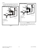
Drain Connection
CHM2480N_SVG
1
1.
Drain connection
Figure 9
Installation
©
Copyright, Alliance Laundry Systems LLC -
DO NOT COPY or TRANSMIT
22
Part No. D1625ENR4
Summary of Contents for IYU180J
Page 2: ......


