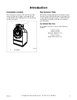
background image

Installation

13

F232158

© Copyright, Alliance Laundry Systems LLC – DO NOT COPY or TRANSMIT
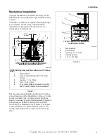
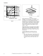
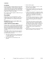
Figure 5 

2. Set machine over bolts and shim the machine so 

that it sits level and is 1/2 inch off the floor. 
Apply machine grout between the floor and all 
frame members of the base of the machine 
(remove front panel and expanded metal back 
panel to gain access to all frame members). Force 
grout under machine base until all voids are 
filled. Refer to 

Figure 5

.

Leave a small opening for water drainage at the 
rear of the machine. Do not omit this step.

3. After grout has cured, place washers and nuts on 

bolts and tighten securely. Be sure nuts are 
tightened evenly all around. DO NOT DISTORT 
MACHINE BY BOLTING DOWN ON AN 
UNEVEN FLOOR SURFACE.

NOTE: Make sure to retighten the anchor bolts 
after a few days of operation.
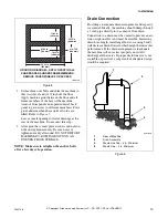
Drain Connection

Providing an adequate drain arrangement and capacity 
is essential. Ideally, the machine should dump through 
a 3 inch pipe directly into a sump or floor drain.

Connection to a drain must be vented to prevent an air-
lock or siphon effect and must be flexible. Increasing 
drain hose length, installing elbows or causing bends 
will decrease drain flow rate which might harm washer 
performance. If the drain arrangement is inadequate, 
the machine will not extract properly nor will it 
discharge all the water. If proper drain line size is not 
available or practical, a surge tank of adequate design 
would be required.

Figure 6 

PHM519N

PHM518N

PHM519N

GROUTING DIAGRAM – APPLY GROUT IN ALL 

SHADED AREAS UNDER FRAME MEMBERS. 

REMOVE COVER PANELS FOR ACCESS.
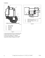
35.63 in.

(905 mm)

27.63 in.

(702 mm)

35.75 in.

(908 mm)

4 in. TYP.
(102 mm)

12.13 in.

(308 mm)

11.63 in.

(295 mm)

PHM528N

1

Rear of Machine

2

Drain Assembly

3

Waste Line Tee – 3 in. Minimum

4

Waste Line – 4 in. Minimum

2

1

3

4

Summary of Contents for POCKET HARDMOUNT UW50P4

Page 1: ... www comlaundry com Washer Extractors Pocket Hardmount WE 6 Control UW50P 4 P031I Part No F232158 September 2002 Keep These Instructions for Future Reference If this machine changes ownership this manual must accompany machine ...

Page 2: ......

Page 3: ...nstallation 7 Specifications and Dimensions 7 Machine Foundation 10 Floor Load Data 10 Mechanical Installation 11 Drain Connection 13 Water Connection 15 Electrical Installation 16 Input Voltage Requirements 16 Connection Specifications 16 Electrical Connection Data 17 Grounding 18 Phase Adder 18 Control Function Test Procedure 18 Maintenance 19 General 19 Daily 19 Monthly 19 Care and Maintenance ...

Page 4: ... Copyright Alliance Laundry Systems LLC DO NOT COPY or TRANSMIT 2 F232158 Notes ...

Page 5: ...technical assistance Replacement Parts If literature or replacement parts are required contact the source from which the machine was purchased or contact Alliance Laundry Systems at 920 748 3950 for the name and address of the nearest authorized parts distributor Customer Service For technical assistance call any of the following numbers 850 718 1025 850 718 1026 Marianna Florida U S A 920 748 312...

Page 6: ...F232158 4 Copyright Alliance Laundry Systems LLC DO NOT COPY or TRANSMIT Notes ...

Page 7: ...e substances give off vapors that could ignite or explode 5 Under certain conditions hydrogen gas may be produced in a hot water system that has not been used for two weeks or more HYDROGEN GAS IS EXPLOSIVE If the hot water system has not been used for such a period before using a washing machine or combination washer dryer turn on all hot water faucets and let the water flow from each for several...

Page 8: ...y the manufacturer of the fabric softener or product 18 Keep washer in good condition Bumping or dropping the washer can damage safety features If this occurs have washer checked by a qualified service person 19 Replace worn power cords and or loose plugs 20 Be sure water connections have a shut off valve and that fill hose connections are tight CLOSE the shut off valves at the end of each wash da...

Page 9: ...r and door shall be fitted with a proper door gasket and a suitable operating door handle A circular door glass of specially treated high tensile strength glass capable of withstanding high mechanical and thermal shock shall be provided Safety Interlock The shell door shall have an interlock device which shall prevent operation of the machine until the door is closed and locked There shall also be...

Page 10: ...PM Extract Speed 700 RPM G Factor Extract 222 Motor Power Wash Speed 0 60 HP 0 45 kW Drain Speed 0 75 HP 0 56 kW Medium Speed 3 0 HP 2 2 kW Extract 3 5 HP 2 6 kW Motor Speed Wash Speed 360 RPM 60 Hertz 290 RPM 50 Hertz Extract Speed 3350 RPM 60 Hertz 2780 RPM 50Hertz Water Connect Size 3 4 in DN20 Operating Pressure 10 120 psi 0 5 8 bar Recommended Pressure 30 85 psi 2 6 bar Maximum Temperature 20...

Page 11: ...tion 9 F232158 Copyright Alliance Laundry Systems LLC DO NOT COPY or TRANSMIT PHM517N 36 in 915 mm 35 62 in 905 mm 63 in 1600 mm 40 in 1016 mm 28 5 in 725 mm 36 in 915 mm 1 in 25 mm 56 in 1420 mm 15 5 in 395 mm ...

Page 12: ...signed to elevate the UW50 to a comfortable and more accessible height for loading and unloading laundry may be used Care must be exercised in the design of such a base due to the force exerted by the machine during extract 222 Gs Static and dynamic loads on the floor or foundation are shown in Table 2 This table can be used as a reference when designing floors and foundations NOTE Machine must be...

Page 13: ...isting of a rigid welded assembly made of reinforcing rod welded to the eight 3 4 inch bolts which may be embedded in the concrete as one piece is also available as an option Refer to Figure 2 Be sure the bolt threads also extend 2 inches above the floor PHM178N NOTE Existing floor must be a minimum of 12 inches thick 1 Machine Base 2 Piece of Angle Welded to Bolt to Prevent Turning 3 Grouting 1 2...

Page 14: ...an fill dirt topped with 12 inches of reinforced concrete Imbed mounting bolts or base frame when pouring concrete Make sure that the bolt threads extend 2 inches above the floor level After the foundation for the machine has been prepared and the concrete has cured proceed as follows 1 Place the machine adjacent to the foundation Do not attempt to move the machine by pushing on the sides Always u...

Page 15: ...ew days of operation Drain Connection Providing an adequate drain arrangement and capacity is essential Ideally the machine should dump through a 3 inch pipe directly into a sump or floor drain Connection to a drain must be vented to prevent an air lock or siphon effect and must be flexible Increasing drain hose length installing elbows or causing bends will decrease drain flow rate which might ha...

Page 16: ...ne 15 1 2 inches from the floor is a 3 inch PVC pipe connection for the drain Drainage is by gravity Figure 8 PHM183N 1 Rear of Machine 2 Drain Assembly 3 Steel Grate 4 Drain Trough 5 Strainer 6 Waste Line PHM183N 3 1 2 4 5 6 TYPICAL TROUGH DRAIN ARRANGEMENT PHM520N 1 Steam Inlet Connection 1 2 in NPT 2 Drain Connection 3 in PVC 3 Water Inlet Connection 3 4 in NPT 4 Door Open PHM520N TOP VIEW 1 2 ...

Page 17: ...oming water connections as follows Four 3 4 inch faucets with 3 4 inch hose bib connected to two 3 4 inch hot water faucet lines and two 3 4 inch cold water faucet lines Figure 9 Each of the hoses should have a screen filter installed to keep rust and other foreign particles out of the solenoid valves These connections should be supplied by a hot and a cold water line at least 3 4 inch size for ea...

Page 18: ...r windings and a separate fuse for the control circuit However a separate three phase circuit breaker must be installed for protection against shorts DO NOT USE FUSES For proper over current protection the circuit breaker should be a 30 Amp capacity unit rated for 208 240 Volts and should be a three phase breaker so that in the event that one leg should be removed from the machine all three legs w...

Page 19: ... to the ground lug If a Delta Supply System is used the high leg must be connected to the red wire L3 at the J box terminal strip If three phase service is not available and a Roto Phase or other phase adder is used the artificial leg must be connected to the red wire L3 Improper connections will result in equipment damage and will void the warranty It is your responsibility to have all electrical...

Page 20: ...e machine should be cleaned when the installation is completed and a function test executed without a load in the machine as follows 1 Check power supply for correct characteristics as to voltage phase and cycles to be sure they are correct for the machine 2 Open manual water shut off valves to the machine 3 Turn on electric power 4 Select Cycle 01 by pressing 0 and 1 on the keyboard and press STA...

Page 21: ...ignment 2 Check motor mounting bolts and clean lint from motor 3 Check all water connections and hose connections for leaks Tighten or replace as needed 4 Remove and clean water inlet valve and hose screen filters Replace if worn or damaged 5 Check anchor bolts tighten if necessary 6 Wipe clean the inside of the washer and check that all electrical components are free of moisture and dust IMPORTAN...

Page 22: ... or acidic solutions are present 4 Discolorations or heat tint from overheating may be removed by scouring with a powder or by employing special chemical solutions 5 Salty or acidic solutions should not be allowed to evaporate and dry on stainless steel They may cause corrosion Wash off the solution after using 6 Permanent direct contact with other materials such as wood or carbon steel should be ...

Page 23: ...l wires and that all connections are secure 4 Check door lock and interlock before starting operation a Attempt to start the washer extractor with door open b Close the door without locking it and attempt to start the washer extractor c Close and lock the door start a cycle and attempt to open the door while the cycle is in progress End of Day 1 Clean the AC drive box filters 2 Clean the door gask...

Page 24: ...________________________ Month __________ Week Ending Checks Observe All Safety Warnings Disconnect power to the washer extractor before performing the weekly maintenance procedures 1 Check the washer extractor for leaks a Start an unloaded cycle to fill the washer extractor b Verify that door and door gasket do not leak c Verify that the drain valve is operating 2 3 4 5 6 7 ...

Page 25: ... replacement or adjustment a Check V belts for uneven wear and frayed edges b Verify that V belts are properly tensioned c Verify that V belts are properly aligned 4 Remove back panel and check hoses for leaks 5 Unlock the hinged lid and check supply dispenser hoses and connections 6 Clean inlet hose filter screens Replace if worn or damaged 7 Tighten motor mounting bolt locknuts and bearing bolt ...

Page 26: ...___ Quarter Checks Observe All Safety Warnings Disconnect power to the washer extractor before performing the quarterly maintenance procedures 1 Tighten door hinges and fasteners if necessary 2 Tighten anchor bolts if necessary 3 Verify that the drain motor shield is in place and secure 4 Check all painted surfaces for bare metal Repair if necessary 5 Clean steam filter if applicable 6 7 8 9 10 11...

Page 27: ...machine c Allow time for residual water in the machine to drain Then disconnect drain hose from the machine 4 Disconnect steam hoses if applicable a Turn off steam supply and allow time for the valves to cool b Disconnect steam hoses from machine 5 Remove the machine from its foundation pad a Keep all panels in place to provide stability when moving the machine b Verify that door is closed and sec...

Page 28: ...F232158 26 Copyright Alliance Laundry Systems LLC DO NOT COPY or TRANSMIT Notes ...

Reviews: