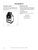


Installation
17
F232158
© Copyright, Alliance Laundry Systems LLC – DO NOT COPY or TRANSMIT
Electrical Connection Data
For Machines with Other Voltages
For Machines with Electric Heat
Use wire size indicated in
Table 7
for runs up to
50 feet. Use next larger size for runs of 50-199 feet.
Use two sizes larger for runs greater than 100 feet.
This protects against voltage drop which would result
in a reduction of starting toque.
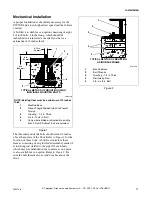
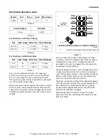
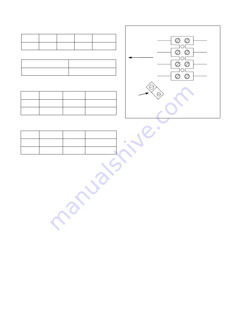
Electrical connections are made at the J-box located on
the rear of the control module. The machine must be
connected to the proper electrical supply shown on the
identification plate attached to the side of the control
module.
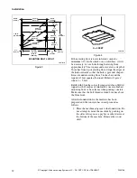
Figure 11
Do not connect the ground to the neutral (N-white
wire) leg at the J-box terminal strip. If the machine is
intended for 4 wire service, a neutral leg must be
provided by the power company. Do not connect the
neutral leg to the ground lug.
If a Delta Supply System is used, the high leg must be
connected to the red wire (L3) at the J-box terminal
strip. If three-phase service is not available and a Roto-
Phase or other phase adder is used, the artificial leg
must be connected to the red wire (L3).
Improper connections will result in equipment damage
and will void the warranty. It is your responsibility to
have all electrical connections made by a properly
licensed and competent electrician. assure that the
electrical installation is adequate.
Rotation should be clockwise in spin. To change
direction of rotation, interchange the black (L1) and
blue (L2) leads.
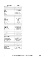
Model
Volt
Phase
Cycle
Max. Amps
UW50
240
3
60
13
Table 4
Circuit Breaker
Wire Size
30 Amp
8 AWG
Table 5
Volt
Max. Amps
Wire Size
Circuit Breaker
440-480
8
10 AWG
25 Amp
380-415
8
10 AWG
25 Amp
Table 6
Volt
Max. Amps
Wire Size
Circuit Breaker
220
65
6 AWG
70 Amp
380-415
37
8 AWG
40 Amp
Table 7
PHM185N
1
Ground Lug Connect to Proven Earth Ground
J-BOX MOUNTED ON REAR OF CONTROL MODULE
White
N
Red
Blue
Black
T (L3)
S (L2)
R (L1)
TO CONTROL
MODULE
1


