background image

Maintenance

801539

66

© Copyright, Alliance Laundry Systems LLC – DO NOT COPY or TRANSMIT

If Service Is Required

If service is required, contact the nearest Factory 
Authorized Service Center.

If you are unable to locate an authorized service center 
or are unsatisfied with the service performed on your 
unit, contact:

Alliance Laundry Systems 
Shepard Street
P.O. Box 990
Ripon, WI 54971-0990
U.S.A.
Phone: (920) 748-3121

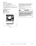
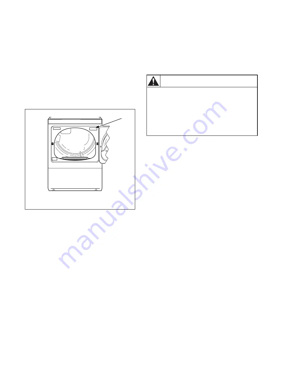
Figure 76 

When calling or writing about your unit, PLEASE 
GIVE THE MODEL AND SERIAL NUMBERS. The 
model and serial numbers are located on the 
nameplate. The nameplate will be in the location 
shown in Figure 76

Please include a copy of your bill of sale and any 
service receipts you have.

D063K

1

Nameplate

1

To reduce the risk of serious injury or death, 
DO NOT repair or replace any part of the unit 
or attempt any servicing unless specifically 
recommended in the user-maintenance 
instructions or in published user-repair 
instructions that you understand and have 
the skills to carry out.

W329

WARNING

Summary of Contents for SWD447C

Page 1: ...her and Dryer Metered Electric and Gas Models SWD446C NOTA El manual en españolaparecedespués del manual en inglés Part No 801539R3 July 2005 Keep These Instructions for Future Reference If this machine changes ownership this manual must accompany machine ...

Page 2: ......

Page 3: ...ow the gas supplier s instructions If you cannot reach your gas supplier call the fire department Installation and service must be performed by a qualified installer service agency or the gas supplier W052 FOR YOUR SAFETY Do not store or use gasoline or other flammable vapors and liquids in the vicinity of this or any other appliance W053 FOR YOUR SAFETY the information in this manual must be foll...

Page 4: ...2 801539 Copyright Alliance Laundry Systems LLC DO NOT COPY or TRANSMIT Notes ...

Page 5: ...l Hoses 17 Step 3 Non Gravity Drain Models Only Connect Drain Hose to Drain Receptacle 19 Step 4 Gravity Drain Models Only Connect Drain Outlet to Drain System 20 Step 5 Gas Dryer Only Connect Gas Supply Pipe 20 Step 6 Electric Dryer Only Connect Electrical Plug 22 Step 7 Connect Dryer Exhaust System 23 Step 8 Position and Level the Unit 24 Step 9 Washer Only Remove the Shock Sleeves and Shipping ...

Page 6: ...ep 3 Add Laundry Supplies 50 Step 4 Determine Proper Controls for Washer 50 Step 5 Set Fabric Selector and Wash Temperature 50 Step 6 Insert Coin s or Card 51 Step 7 Start Washer 51 Indicator Lights 52 Operation Instructions for NetMaster Washers 53 Step 1 Load Laundry 53 Step 2 Close Loading Door 53 Step 3 Add Laundry Supplies 53 Step 4 Determine Proper Controls for Washer 54 Step 5 Set Fabric Se...

Page 7: ...abric Selector 60 Step 6 Insert Coin s or Card 60 Step 7 Start Dryer 61 Indicator Lights 61 Maintenance 63 User Maintenance Instructions 63 Lubrication 63 Cold Weather Care 63 Vacations and Extended Non Use 63 Care of Your Washer 63 Replacing Hoses 63 Filter Screen 63 Care of Your Dryer 63 Exhaust System 64 For Energy Conservation 64 Before You Call for Service 65 If Service Is Required 66 Informa...

Page 8: ...6 801539 Copyright Alliance Laundry Systems LLC DO NOT COPY or TRANSMIT Notes ...

Page 9: ...acement Parts If replacement parts are required contact the source from which you purchased your unit or contact Alliance Laundry Systems Shepard Street P O Box 990 Ripon WI 54971 0990 U S A Phone 920 748 3950 for the name and address of the nearest authorized parts distributor ...

Page 10: ...801539 8 Copyright Alliance Laundry Systems LLC DO NOT COPY or TRANSMIT Notes ...

Page 11: ...mmable or explosive substances as they give off vapors that could ignite or explode 4 Under certain conditions hydrogen gas may be produced in a hot water system that has not been used for two weeks or more HYDROGEN GAS IS EXPLOSIVE If the hot water system has not been used for such a period before using a washing machine or combination washer dryer turn on all hot water faucets and let the water ...

Page 12: ...r from fuel combustion which can cause death or serious illness and which are known to the State of California to cause cancer birth defects or other reproductive harm 19 Washer and dryer will not operate with the loading door open DO NOT bypass the door safety switches by permitting the washer or dryer to operate with the doors open The washer and dryer will stop tumbling when the doors are opene...

Page 13: ...nels removed 34 DO NOT operate the unit with missing or broken parts 35 DO NOT bypass any safety devices 36 Failure to install maintain and or operate this machine according to the manufacturer s instructions may result in conditions which can produce bodily injury and or property damage 37 Do not operate washer and dryer if the units have been separated IMPORTANT Solvent vapors from dry cleaning ...

Page 14: ...801539 12 Copyright Alliance Laundry Systems LLC DO NOT COPY or TRANSMIT Notes ...

Page 15: ...that are listed throughout this manual SWD619N With leveling legs turned into base SWD620N With leveling legs turned into base 1 3 8 in N P T Gas Connection SWD619N 23 5 in 59 7 cm 2 0 in 5 1 cm 7 0 in 17 8 cm 17 5 in 44 8 cm 14 3 in 36 3 cm 28 in 71 1 cm 29 6 in 75 1 cm 31 1 in 79 cm 76 5 in 194 3 cm 45 8 in 116 3 cm 15 4 in 39 1 cm 26 9 in 68 3 cm 2 0 in 5 1 cm ELECTRIC DRYERS WITH OLD STYLE DOO...

Page 16: ... that are listed throughout this manual SWD741N With leveling legs turned into base SWD742N With leveling legs turned into base 1 3 8 in N P T Gas Connection SWD741N 23 5 in 59 7 cm 2 0 in 5 1 cm 7 0 in 17 8 cm 18 7 in 47 5 cm 14 3 in 36 3 cm 28 in 71 1 cm 29 6 in 75 1 cm 31 1 in 79 cm 76 5 in 194 3 cm 45 8 in 116 3 cm 15 4 in 39 1 cm 26 9 in 68 3 cm ELECTRIC DRYERS WITH NEW STYLE DOOR 8 0 in 20 3...

Page 17: ...d the dryer than the clearances that are listed throughout this manual SWD743N With leveling legs turned into base SWD744N With leveling legs turned into base 1 3 8 in N P T Gas Connection SWD743N 23 5 in 59 7 cm 2 0 in 5 1 cm 7 0 in 17 8 cm 18 7 in 47 5 cm 14 3 in 36 3 cm 28 in 71 1 cm 29 6 in 75 1 cm 31 1 in 79 cm 76 5 in 194 3 cm 45 8 in 116 3 cm 15 4 in 39 1 cm 26 9 in 68 3 cm ELECTRIC DRYERS ...

Page 18: ... metal duct and exhaust the dryer to the outside by the shortest route possible NOTE For more detailed information refer to section on Dryer Exhaust Requirements Figure 2 Electrical WASHER Refer to serial plate for specific electrical requirements For more detailed information refer to section on Washer Electrical Requirements ELECTRIC DRYER Dryer needs a 3 or 4 wire 120 240 or 120 208 Volt 60 Her...

Page 19: ... should not be reused Turn on the water supply faucets and flush the lines for approximately two minutes to remove any foreign materials that could clog the screens in the water mixing valve NOTE When installing in newly constructed or renovated building it is very important to flush the lines since build up may have occurred during construction Remove the two filter screens and the two plain rubb...

Page 20: ...natural rubber parts deteriorate after extended use Hoses may develop cracks blisters or material wear from the temperature and constant high pressure they are subjected to All hoses should be checked on a yearly basis for any visible signs of deterioration Any hose showing the signs of deterioration listed above should be replaced immediately All hoses should be replaced every five years TLW1976N...

Page 21: ...imum of 1 3 8 inch 3 5 cm outside diameter drain hose Figure 6 Standpipe Installation Place the drain hose into the standpipe Remove the beaded tie down strap from accessories bag and place around standpipe and drain hose and tighten strap to hold hose to standpipe This will prevent the drain hose from dislodging from drain receptacle during use Figure 7 SWD622N 1 Shipping Tape 1 SWD623N 1 Drain H...

Page 22: ...re 8 Step 5 Gas Dryer Only Connect Gas Supply Pipe For further assistance refer to section on Gas Requirements 1 Make certain dryer is equipped for use with the type of gas in laundry room Dryer is equipped at the factory for Natural Gas with a 3 8 inch N P T gas connection 2 Remove the shipping cap from the gas connection at the rear of the dryer Make sure you do not damage the pipe threads when ...

Page 23: ...ector Use only if allowed by local codes Use Design A G A Certified Connector 4 Black Iron Pipe Shorter than 20 ft 6 1 m Use 3 8 in pipe Longer than 20 ft 6 1 m Use 1 2 in pipe 2 1 8 in N P T Pipe Plug For checking inlet gas pressure 5 3 8 in N P T Gas Connection 3 Equipment Shut Off Valve Installed within 6 ft 1 8 m of dryer 1 5 4 2 3 ...

Page 24: ...rical Requirements NOTE Four wire cord is required for mobile homes or where codes do not permit grounding through neutral Figure 11 D275I D006I 1 Typical Receptacle 2 Power Cord Not supplied with dryer 3 Strain Relief Nut 4 Strain Relief 1 2 3 4 THREE WIRE 1 2 3 4 FOUR WIRE D679I D680I NOTE Dryer is shown with access cover removed for illustration purposes only NEVER operate the dryer with access...

Page 25: ... rigid or flexible metal duct The male end of each section of duct must point away from the dryer Use as few elbows as possible Use duct tape or pop rivets on all duct joints Ductwork that runs through unheated areas must be insulated to help reduce condensation and lint build up on pipe walls Failure to exhaust dryer properly will void warranty Figure 12 NOTE Venting materials are not supplied wi...

Page 26: ...n four feet across floor if the leveling legs have been extended as legs and base could become damaged NOTE Use of the dispenser drawer or washer or dryer doors as handles in the transportation of the unit may cause damage to the dispenser or doors Remove rubber feet from accessories bag and place on all four leveling legs NOTE For further assistance refer to section on Location Requirements Verif...

Page 27: ... the accessories bag Save materials for use whenever the unit is moved NOTE The shipping materials MUST be reinstalled whenever the unit is moved Refer to Moving Unit to a New Location section for proper instructions on reinstalling the shipping materials Reinstall front access panel IMPORTANT DO NOT tip washer more than 6 inches 152 4 mm in any direction after shipping brace has been removed Shoc...

Page 28: ...tallation of Shipping Materials Disconnect unit from electrical supply Remove front access panel by removing two screws Place the shock sleeves on all four shock absorbers Refer to Figure 20 Insert hooked end of shipping brace into the open slot of the motor mount Attach with bolts and lockwashers Refer to Figure 20 Reinstall front access panel Figure 20 Refer to step 8 for proper procedures whene...

Page 29: ...T If igniter does not light make sure gas is turned on After dryer has operated for approximately five minutes observe burner flame Adjust the air shutter to obtain a soft uniform blue flame A lazy yellow tipped flame indicates lack of air A harsh roaring very blue flame indicates too much air Adjust the air shutter as follows 1 Loosen the air shutter lockscrew 2 Turn the air shutter to the left t...

Page 30: ...d with the washer if it will not fit the outlet have a proper outlet installed by a qualified electrician NOTE Have a qualified electrician check the polarity of the wall receptacle If a voltage reading is measured other than that illustrated the qualified electrician should correct the problem D009I To reduce the risk of fire electric shock serious injury or death all wiring and grounding MUST co...

Page 31: ... fused on both sides of the line ELECTRICAL SERVICE FOR THE DRYER SHOULD BE OF MAXIMUM RATED VOLTAGE LISTED ON THE NAMEPLATE DO NOT CONNECT DRYER TO 110 115 OR 120 VOLT CIRCUIT Heating elements are available for field installation in dryers which are to be connected to electrical service of different voltage than that listed on nameplate such as 208 Volt D799I 1 L1 2 Ground 3 Neutral Side 4 Round ...

Page 32: ...ral 120 240 Volt 60 Hertz AC 1 Phase Service Entrance Switch Box Refer to NOTE above 4 Metallic or Non Metallic Sheathed Cable Copper wire only 5 Pigtail to Dryer Refer to NOTE above 2 30 Ampere Fuses or Circuit Breaker 6 Neutral 3 Neutral Wire 7 Terminal Block in Dryer NOTE The power cord pigtail is NOT supplied with the electric dryer Type of pigtail and gauge of wire must conform to local codes...

Page 33: ... cord kit rated 240 Volts minimum 30 Amperes and labeled as suitable for use in a clothes dryer 3 Tighten these wire binding screws firmly IMPORTANT Failure to tighten these screws firmly may result in wire failure at the terminal block 4 Secure the strain relief to the power cord or wires where they enter the dryer cabinet 5 Check the continuity of the ground connection before plugging the cord i...

Page 34: ...ryer 3 Neutral Terminal 9 Power Cord or Direct Wiring Three Wire 4 Terminal Block 10 Access Cover 5 L2 Terminal 11 Terminal Bracket Ground Screw 6 Slotted Hex Head Screws Shipped inside the dryer 12 Ground Wire 12 1 2 3 4 5 6 7 8 9 10 11 Dryer unit is shown with the access cover removed for illustration purposes only To reduce the risk of an electric shock NEVER operate the dryer unit with the acc...

Page 35: ...the hole in the rear of the dryer cabinet Install the strain relief nut from the inside of the cabinet and tighten firmly 7 Attach the green ground wire from the four wire power cord to the terminal block mounting bracket using the hex head screw removed in step 4 Tighten the screw firmly 8 Using the three wire binding 10 32 x 3 8 inch screws from the accessories bag located inside the cylinder un...

Page 36: ...n 801539 34 Copyright Alliance Laundry Systems LLC DO NOT COPY or TRANSMIT Figure 27 D815I 1 Typical Four Wire Receptacle 2 Four Wire Power Cord Not supplied with dryer 3 Strain Relief Nut 4 Strain Relief 1 4 2 3 ...

Page 37: ... Four Wire 4 Black Wire 11 Red Wire 5 Terminal Block 12 Terminal Bracket Ground Screw 6 L2 Terminal 13 L1 Terminal 7 Slotted Hex Head Screws Shipped inside the dryer or removed in step 2 D683I 1 1 2 3 4 5 6 7 8 9 10 11 4 12 13 11 Dryer unit is shown with the access cover removed for illustration purposes only To reduce the risk of an electric shock NEVER operate the dryer unit with the access cove...

Page 38: ... OTHER APPLIANCES ON THE SAME CIRCUIT WHEN THIS APPLIANCE IS OPERATING DO NOT OVERLOAD CIRCUITS DO NOT operate both a washer and gas dryer on the same circuit Use separately fused 15 Amp circuits Figure 29 To reduce the risk of fire electric shock or personal injury all wiring and grounding MUST conform with the latest edition of the National Electrical Code ANSI NFPA 70 or the Canadian Electrical...

Page 39: ...provided with the dryer unit if it will not fit the outlet have a proper outlet installed by a qualified electrician If the laundry room s electrical supply does not meet the above specifications and or if you are not sure the laundry room has an effective ground have a qualified electrician or your local electrical utility company check it and correct any problems D799I 1 L1 2 Ground 3 Neutral Si...

Page 40: ...pressure testing of that system at test pressures in excess of 1 2 psi 3 45 kPa NOTE When connecting to a gas line an equipment shutoff valve must be installed within 6 feet 1 8 m of the dryer An 1 8 N P T pipe plug must be installed as shown Refer to Figure 31 Natural Gas Altitude Adjustments Altitude Orifice Size Part Number feet m inches mm 2 000 610 41 0 0960 2 44 503776 3 000 915 42 0 0935 2 ...

Page 41: ...nector Use only if allowed by local codes Use Design A G A Certified Connector 4 Black Iron Pipe Shorter than 20 ft 6 1 m Use 3 8 in pipe Longer than 20 ft 6 1 m Use 1 2 in pipe 2 1 8 in N P T Pipe Plug For checking inlet gas pressure 5 3 8 in N P T Gas Connection 3 Equipment Shut Off Valve Installed within 6 ft 1 8 m of dryer 1 5 4 2 3 ...

Page 42: ...l Hose 8 feet 2 44 m No 20618 Fill Hose 10 feet 3 05 m Figure 32 Water Pressure Pressure must be a minimum of 20 to a maximum of 120 pounds per square inch 138 to 827 kPa static pressure measured at the faucet NOTE Water pressure under 20 pounds per square inch 138 kPa will cause an extended fill time in the washer and may not properly flush out the detergent dispenser Risers Risers or air cushion...

Page 43: ...to back IMPORTANT Unless completely assembled DO NOT slide the unit across the floor DO NOT slide the unit more than four feet once the leveling legs have been extended as the legs and the base could become damaged The unit needs sufficient clearance and an adequate air supply for proper operation and ventilation and for easier installation and servicing Minimum clearances are shown in Figure 34 F...

Page 44: ...reduce the risk of fire and combustion gas accumulation the dryer MUST be exhausted to the outdoors W116 This gas appliance contains or produces a chemical or chemicals which can cause death or serious illness and which are known to the State of California to cause cancer birth defects or other reproductive harm To reduce the risk from substances in the fuel or from fuel combustion make sure this ...

Page 45: ...ir exchanger that can accommodate on demand make up air needs in the laundry room These devices can be obtained through your building contractor or building material suppliers Don t Draw make up air from a room containing a gas fired water heater Draw make up air from a room containing a dry cleaner or a hair salon Exhaust Direction The dryer can be exhausted to the outdoors through the back left ...

Page 46: ...he ground Larger clearances may be necessary for installations where heavy snowfall can occur Number of 90 Elbows Weather Hood Type Recommended Use Only for Short Run Installations Maximum length of 4 in 10 2 cm diameter rigid metal duct 0 65 feet 19 8 m 55 feet 16 8 m 1 55 feet 16 8 m 47 feet 14 3 m 2 47 feet 14 3 m 41 feet 12 5 m 3 36 feet 11 0 m 30 feet 9 1 m 4 28 feet 8 5 m 22 feet 6 7 m Maxim...

Page 47: ...ipment at extra cost The kit comes in two halves that can be separately attached to the dryer and wall outlet Once attached the unit can be slid back into position Figure 37 Dryer Airflow Efficient dryer operation requires proper dryer airflow Proper dryer airflow can be evaluated by measuring the static pressure Static pressure in the dryer s exhaust duct should be no greater than that shown in F...

Page 48: ...Installing an exhaust system does not eliminate the necessity of cleaning the dryer lint filter before each load The dryer interior and the complete exhaust system should be cleaned periodically by a qualified service person to remove any lint build up A Backdraft Damper Part No 58786 obtain locally should be installed in a 4 inch 10 2 cm diameter VERTICAL duct system only This will prevent a back...

Page 49: ... or Clearance Per Local Codes 5 NOTE Where the exhaust duct pierces a combustible wall or ceiling an opening must be sized as shown or per local codes 1 3 2 4 5 CONNECT TO DRYER VERTICAL EXHAUST INSTALLATION Duct Station Minimum Diameter of Collector Duct A 4 inches 10 2 cm B 8 inches 20 3 cm C 9 inches 22 9 cm D 10 inches 25 4 cm E 11 inches 27 9 cm F 12 inches 30 5 cm G 13 inches 32 6 cm H 14 in...

Page 50: ...of air through the dryer thus reducing the efficiency of the dryer The clothes will take longer to dry and energy will be wasted Figure 42 Dryer Motor Overload Protector The motor overload protector stops the motor in the event of an overload After cooling the overload protector will reset itself The dryer can be restarted by pressing the START keypad If the overload protector cycles again remove ...

Page 51: ...nd water solution and a damp cloth to remove shipping dust from inside of washer drum IMPORTANT Remove all sharp objects from laundry to avoid tears and rips to items during normal machine operation Step 1 Load Laundry Load items loosely into wash drum Figure 43 Step 2 Close Loading Door Close loading door tightly The washer will not operate with the loading door open Figure 44 SWD751N SWD752N ...

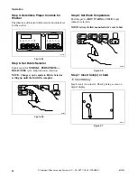
Page 52: ...ure 45 Step 4 Determine Proper Controls for Washer The direction of the arrow indicates which controls are for the washer Figure 46 Step 5 Set Fabric Selector and Wash Temperature Push keypad for NORMAL HOT NORMAL WARM PERM PRESS WARM or DELICATES COLD cycle Light indicates selection NOTE Changes can be made to Fabric Selector setting up until the first fill is complete Figure 47 SWD753N 1 Deterge...

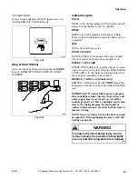
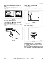
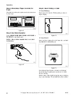
Page 53: ...s or Card To Insert Money Insert coin s in coin slot Check pricing as seen on digital display Figure 48 To Insert Card Insert card into opening Figure 49 Step 7 Start Washer After vend price has been satisfied push the START keypad DOOR MUST BE CLOSED TO START WASHER Figure 50 W387I DRY1927N FLW1923N F ...

Page 54: ...locked The door cannot be opened when this light is on IMPORTANT If washer fails to operate properly after installation make sure electrical service and water supply faucets are turned on Are all the controls properly set Have a qualified serviceman refer to the wiring diagram located inside of washer control cabinet check for broken loose or incorrect wiring NOTE Once a cycle has started the door...

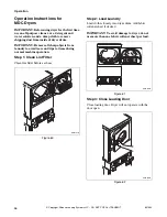
Page 55: ...ly into wash drum Figure 51 Step 2 Close Loading Door Close loading door tightly The washer will not operate with the loading door open Figure 52 Step 3 Add Laundry Supplies Open dispenser drawer Measure and add low sudsing detergent 1 bleach 2 and fabric softener 3 to the dispenser drawer Refer to Figure 53 Close dispenser drawer IMPORTANT If using detergents made for topload washers avoid oversu...

Page 56: ...ection NOTE Changes can be made to Fabric Selector setting up until the first fill is complete Figure 55 Step 6 Set Wash Temperature Push keypad for HOT WARM or COLD Light indicates selection NOTE Always follow manufacturer s care labels Figure 56 Step 7 Insert Coin s or Card To Insert Money Insert coin s in coin slot Check pricing as seen on digital display Figure 57 W527I H205I W527I H205I HOT W...

Page 57: ...it to prompt the user to insert coins or a card to satisfy the vend price When INSERT COIN CARD is lit the digits and decimal point show the vend price remaining to be satisfied REMOVE CARD Card Models Only REMOVE CARD flashes after the START keypad has been pressed and the vend has been deducted from the card IMPORTANT If washer fails to operate properly after installation make sure electrical se...

Page 58: ...ORTANT Remove all sharp objects from laundry to avoid tears and rips to items during normal machine operation Step 1 Clean Lint Filter Clean lint filter before each use Figure 60 Step 2 Load Laundry Load clothes loosely into dryer drum Add fabric softener sheet if desired IMPORTANT To avoid damage to dryer do not use more than one fabric softener sheet per load Figure 61 Step 3 Close Loading Door ...

Page 59: ...lways follow manufacturer s care label instructions Figure 64 Step 6 Insert Coin s or Card To Insert Money Insert coin s in coin slot Check pricing as seen on digital display Figure 65 To Insert Card Insert card into opening Figure 66 If Additional Time Feature is turned on additional dryer time may be purchased at cycle start or while dryer is running Remove knits when slightly damp because overd...

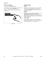
Page 60: ...he dryer is not in a cycle the full vend price has been satisfied and the dryer door is closed When the START keypad is pressed the cycle will begin or resume DRYING DRYING is lit to indicate that one of the heated cycles HIGH TEMP MED TEMP LOW TEMP or DELICATES is currently in operation DRYING will turn off at the end of a heated cycle or when the COOL DOWN cycle begins COOL DOWN COOL DOWN is lit...

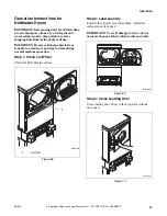
Page 61: ...T Remove all sharp objects from laundry to avoid tears and rips to items during normal machine operation Step 1 Clean Lint Filter Clean lint filter before each use Figure 68 Step 2 Load Laundry Load clothes loosely into dryer drum Add fabric softener sheet if desired IMPORTANT To avoid damage to dryer do not use more than one fabric softener sheet per load Figure 69 Step 3 Close Loading Door Close...

Page 62: ... s care label instructions Figure 72 Step 6 Insert Coin s or Card To Insert Money Insert coin s in coin slot Check pricing as seen on digital display Figure 73 To Insert Card Insert card into opening Do not remove the card until the REMOVE CARD LED is lit Figure 74 If Additional Time Feature is turned on additional dryer time may be purchased at cycle start or while dryer is running Remove knits w...

Page 63: ...d and the dryer door is closed When the START keypad is pressed the cycle will begin or resume DRYING DRYING is lit to indicate that one of the heated cycles HIGH TEMP MED TEMP LOW TEMP is currently in operation DRYING will turn off at the end of a heated cycle or when the COOL DOWN cycle begins COOL DOWN COOL DOWN is lit whenever the COOL DOWN portion of a heated cycle is active It is also lit wh...

Page 64: ...801539 62 Copyright Alliance Laundry Systems LLC DO NOT COPY or TRANSMIT Notes ...

Page 65: ...d window cleaner Replacing Hoses Hoses and other natural rubber parts deteriorate after extended use Hoses may develop cracks blisters or material wear from the temperature and constant high pressure they are subjected to All hoses should be checked on a yearly basis for any visible signs of deterioration Any hose showing the signs of deterioration listed above should be replaced immediately All h...

Page 66: ... obstruct the flow of combustion and ventilation air NOTE Verify proper operation after servicing For Energy Conservation Make sure the lint filter is always clean Do not overload dryer Do not overdry clothes Remove items to be ironed while still damp Large loads of similar fabrics dry the most efficiently However dry permanent press in smaller loads to prevent wrinkling Use the correct temperatur...

Page 67: ...t coin s or card Does Not Start Does Not Heat Does Not Dry Clothes Satisfactorily Possible Reason Do This to Correct Insert coin s or card Be sure the cord is plugged all the way into the electrical outlet Close the loading door Make sure the controls are in a HEAT setting Press the START keypad Has the laundry room fuse blown or become loosened or is a circuit breaker OFF The dryer itself does NO...

Page 68: ... 3121 Figure 76 When calling or writing about your unit PLEASE GIVE THE MODEL AND SERIAL NUMBERS The model and serial numbers are located on the nameplate The nameplate will be in the location shown in Figure 76 Please include a copy of your bill of sale and any service receipts you have D063K 1 Nameplate 1 To reduce the risk of serious injury or death DO NOT repair or replace any part of the unit...

Page 69: ...ance Laundry Systems Shepard Street P O Box 990 Ripon WI 54971 0990 U S A Date Purchased Model Number Serial Number Dealer s Name Dealer s Address Phone Number Service Agency Service Agency Address Phone Number NOTE Record the above information and keep your sales slip Model and serial numbers are located on the nameplate ...

Page 70: ......

Page 71: ... y secadora de montaje vertical con contador de monedas Modelos eléctricos y a gas SWD446C Pieza No 801539R3 Julio 2005 Guarde estas instrucciones para referencia en el futuro Si la unidad cambia de dueño asegúrese de que este manual vaya con la misma ...

Page 72: ......

Page 73: ...no Seguir las instrucciones del proveedor de gas Si no puede comunicarse con su proveedor de gas llame a los bomberos La instalación y servicio tienen que ser ejecutados por un instalador cualificado una agencia de servicio o su proveedor de gas W052SPR3 PARA SU SEGURIDAD No almacene ni use gasolina u otros líquidos o vapores inflamables cerca de éste o de otro aparato cualquiera W053S2 PARA SU SE...

Page 74: ...72 801539 SP Copyright Alliance Laundry Systems LLC DO NOT COPY or TRANSMIT Notas ...

Page 75: ... desagüe 89 Paso 4 Únicamente modelos con desagüe por gravedad Conecte la salida del desagüe al sistema de desagüe 90 Paso 5 Sólo para secadoras a gas Conecte el tubo de suministro de gas 90 Paso 6 Sólo para secadoras eléctricas Conecte el enchufe de suministro de energía eléctrica 92 Paso 7 Conecte el sistema de escape de la secadora 93 Paso 8 Coloque la unidad en su lugar y nivélela 94 Paso 9 Só...

Page 76: ...a temperatura de lavado 122 Paso 6 Inserte la s moneda s o la tarjeta 123 Paso 7 Arranque la lavadora 123 Luces indicadoras 124 Instrucciones para la operación de lavadoras NetMaster 125 Paso 1 Cargue la lavadora 125 Paso 2 Cierre la puerta de carga 125 Paso 3 Agregue los suministros para lavar 126 Paso 4 Determine los controles apropiados para la lavadora 126 Paso 5 Ajuste el selector de tela 126...

Page 77: ...34 Luces indicadoras 134 Mantenimiento 135 Instrucciones de mantenimiento para el usuario 135 Lubricación 135 Cuidados en climas fríos 135 Vacaciones y falta de uso durante un período prolongado 135 Cuidado de la lavadora 135 Reemplazo de mangueras 135 Rejillas del filtro 135 Cuidado de la secadora 136 Sistema de escape 136 Conservación de la energía 136 Antes de llamar para solicitar servicio de ...

Page 78: ...76 801539 SP Copyright Alliance Laundry Systems LLC DO NOT COPY or TRANSMIT Notas ...

Page 79: ...equiere piezas de repuesto póngase en contacto con el establecimiento donde adquirió la máquina o con Alliance Laundry Systems Shepard Street P O Box 990 Ripon WI 54971 0990 U S A Teléfono 920 748 3950 para obtener el nombre y la dirección del distribuidor autorizado de piezas de repuesto más cercano ...

Page 80: ...801539 SP 78 Copyright Alliance Laundry Systems LLC DO NOT COPY or TRANSMIT Notas ...

Page 81: ... inflamables o explosivas Estas sustancias despiden gases que pueden encenderse o explotar 4 En ciertos casos cuando no se utiliza el sistema de agua caliente durante dos semanas o más puede almacenarse gas hidrógeno en dicho sistema EL GAS HIDRÓGENO ES EXPLOSIVO Si no ha utilizado el sistema de agua caliente durante dos semanas o más antes de usar la lavadora o la combinación de lavadora secadora...

Page 82: ...cáncer deformaciones congénitas y otros efectos dañinos sobre la reproducción 19 La lavadora y la secadora no funcionan con la puerta de carga abierta NO ANULE los interruptores de seguridad de las puertas permitiendo así que la lavadora o la secadora funcione con la puerta abierta La lavadora y la secadora se detienen cuando las puertas se abren No utilice la lavadora o la secadora si no deja de ...

Page 83: ...onga a funcionar la unidad sin los protectores o paneles correspondientes 34 NO utilice la unidad si le faltan piezas o tiene piezas dañadas 35 NO anule ningún dispositivo de seguridad 36 El incumplimiento de las instrucciones del fabricante para la instalación mantenimiento u operación de la máquina podría derivar en situaciones causantes de lesiones personales o daños a la propiedad 37 No haga f...

Page 84: ...801539 SP 82 Copyright Alliance Laundry Systems LLC DO NOT COPY or TRANSMIT Notas ...

Page 85: ... mayor que los indicados en este manual SWD619N Con las patas de totalmente dentro de la base SWD620N Con las patas de totalmente dentro de la base 1 Conexión de gas N P T de 3 8 plg SWD619N 23 5 plg 59 7 cm 2 0 plg 5 1 cm 7 0 plg 17 8 cm 17 5 plg 44 8 cm 28 plg 71 1 cm 29 6 plg 75 1 cm 31 1 plg 79 cm 76 5 plg 194 3 cm 45 8 plg 116 3 cm 15 4 plg 39 1 cm 26 9 plg 68 3 cm 2 0 plg 5 1 cm SECADORAS EL...

Page 86: ...indicados en este manual SWD741N Con las patas de totalmente dentro de la base SWD742N Con las patas de totalmente dentro de la base 1 Conexión de gas N P T de 3 8 plg SWD741N 23 5 plg 59 7 cm 2 0 plg 5 1 cm 7 0 plg 17 8 cm 18 7 plg 47 5 cm 14 3 plg 36 3 cm 28 plg 71 1 cm 29 6 plg 75 1 cm 31 1 plg 79 cm 76 5 plg 194 3 cm 45 8 plg 116 3 cm 15 4 plg 39 1 cm 26 9 plg 68 3 cm 2 0 plg 5 1 cm SECADORAS ...

Page 87: ...ecadora recomendamos dejar un espacio libre mayor que los indicados en este manual SWD743N Con las patas de totalmente dentro de la base SWD744N Con las patas de totalmente dentro de la base 1 Conexión de gas N P T de 3 8 plg SWD743N 23 5 plg 59 7 cm 2 0 plg 5 1 cm 7 0 plg 17 8 cm 18 7 plg 47 5 cm 14 3 plg 36 3 cm 28 plg 71 1 cm 29 6 plg 75 1 cm 31 1 plg 79 cm 76 5 plg 194 3 cm 45 8 plg 116 3 cm 1...

Page 88: ...a más corta posible para el escape de la secadora NOTA Para obtener más detalles consulte la sección de Requisitos del sistema de escape de la secadora Figura 2 Requisitos eléctricos LAVADORA Consulte la placa de identificación para determinar los requisitos eléctricos específicos Para obtener más detalles consulte la sección de Requisitos eléctricos de la lavadora SECADORA ELÉCTRICA La secadora n...

Page 89: ...ua fluya por aproximadamente dos minutos para eliminar cualquier material extraño que pueda obstruir las mallas de la válvula para mezclar el agua NOTA Cuando instale la lavadora en un local recién construido o remodelado debe limpiar las tuberías dejando que el agua fluya ya que pudo haberse acumulado material en las mismas durante la construcción Saque de la bolsa de accesorios las dos rejillas ...

Page 90: ...se deterioran después de períodos prolongados de uso En las mangueras pueden producirse grietas poros o desgaste del material debido a la temperatura y a la elevada presión constante a que están sometidas Todas las mangueras deben revisarse cada año para detectar posibles indicios de deterioro Cualquier manguera que muestre alguno de los indicios de deterioro indicados anteriormente deberá ser ree...

Page 91: ...omo mínimo Figura 6 Instalación del tubo vertical de desagüe Coloque la manguera de desagüe dentro del tubo vertical de desagüe Saque la abrazadera perlada de la bolsa de accesorios colóquela alrededor del tubo vertical de desagüe y la manguera de desagüe y apriete la correa para sujetar la manguera al tubo vertical de desagüe Así se evita que se salga la manguera del receptáculo de desagüe cuando...

Page 92: ...ecte el tubo de suministro de gas Remítase a la sección de Requisitos de la fuente de suministro de gas para obtener más información 1 Asegúrese de que la secadora esté equipada para trabajar con el tipo de gas utilizado en el área de lavandería La secadora viene equipada de fábrica con una conexión de gas N P T de 3 8 plg para trabajar con gas natural 2 Retire la tapa utilizada para fines de emba...

Page 93: ...locales utilice un conector con diseño certificado por A G A 4 Tubo de hierro negro Menos de 20 pies 6 1 m utilice tubo de 3 8 plg Más de 20 pies 6 1 m utilice tubo de 1 2 plg 5 Conexión de gas N P T de 3 8 plg 2 Tapón para tubo N P T de 1 8 plg para medir la presión de entrada del gas 3 Válvula de cierre del equipo instale a una distancia máxima de 6 pies 1 8 m de la secadora 1 5 4 2 3 ...

Page 94: ...talaciones en viviendas móviles o en áreas en las que los códigos no permitan una conexión a tierra a través del cable neutro Figura 11 D275I D006I 1 Receptáculo normal 2 Cordón de suministro de energía eléctrica no viene con la secadora 3 Tuerca de protector contra tirones 4 Protector contra tirones 1 2 3 4 ENCHUFE DE TRES CONDUCTORES 1 2 3 4 ENCHUFE DE CUATRO CONDUCTORES D679I D680I NOTA En este...

Page 95: ...s secciones del conducto deberá apuntar hacia el lado opuesto a la secadora Use el menor número de codos que sea posible Use cinta adhesiva para conductos o remaches en todas las uniones del conducto Las secciones del conducto que pasen a través de áreas no calentadas deberán aislarse para reducir la condensación y la acumulación de pelusas en las paredes del conducto La garantía queda sin efecto ...

Page 96: ...nar NOTA NO deslice la unidad sobre el piso con las patas niveladoras extendidas ya que podrían resultar dañadas NOTA El uso de la gaveta del surtidor o de la puerta de la unidad como agarradera al transportar la unidad puede dañar el surtidor o la puerta Saque las patas de goma que vienen en la bolsa de accesorios y colóquelas en las patas de nivelación NOTA Si necesita más asistencia consulte la...

Page 97: ...ansporte la lavadora por el frente o sin haber instalado previamente los materiales de transporte Guarde los materiales de transporte en la bolsa provista dentro de la bolsa de accesorios Conserve los materiales para usarlos cuando haya que desplazar la lavadora NOTA Los materiales de transporte DEBERÁN reinstalarse al mover la unidad de un lugar a otro Las instrucciones para reinstalar estos mate...

Page 98: ...ueda haber caído en los tambores durante el transporte Figura 15 Figura 16 Paso 11 Enchufe la lavadora y la secadora Véase las seccións de Requisitos eléctricos y conecte la lavadora y la secadora a un receptáculo de pared Figura 17 Figura 18 Figura 19 SWD747N H315I D254I D275I D254I D254I LAVADORA Enchufe el cordón en un circuito independiente de 15 amperios protegido con fusible SECADORA ELÉCTRI...

Page 99: ...ecte la undidad de la fuente de alimentación eléctrica Saque el panel de acceso frontal retirando dos tornillos Coloque los manguitos de amortiguador sobre los cuatro amortiguadores Consulte la Figura 20 Inserte el lado en forma de gancho del tirante sujetador de embarque dentro de la ranura del montaje del motor Asegure con pernos y arandelas de seguridad Consulte la Figura 20 Reinstale el panel ...

Page 100: ...de que la secadora haya estado funcionando durante aproximadamente cinco minutos observe la llama del quemador Ajuste el obturador de aire para obtener una llama azul suave y uniforme Una llama débil con las puntas amarillas es indicio de falta de aire Una llama azul ruidosa y muy fuerte revela que hay demasiado aire Ajuste el obturador de aire de la manera siguiente 1 Afloje el tornillo de fijaci...

Page 101: ...los servicios de un electricista calificado para que le instale el receptáculo de pared apropiado NOTA Llame a un electricista calificado para que revise la polaridad del receptáculo de pared Si la lectura del voltaje difiere de la que aparece en la ilustración el electricista debe solucionar el problema D009I Para reducir el riesgo de incendio descarga eléctrica o lesiones personales todo el cabl...

Page 102: ...por ambos lados de la línea EL SUMINISTRO DE ENERGÍA ELÉCTRICA DEBERÁ SER DEL VOLTAJE MÁXIMO INDICADO EN LA PLACA DE IDENTIFICACIÓN NO CONECTE LA SECADORA A UN CIRCUITO DE 110 115 O 120 VOLTIOS Están disponibles elementos calentadores para instalación en el campo en secadoras que van a conectarse a una fuente de suministro de energía eléctrica con un voltaje diferente al que aparece en la placa de...

Page 103: ...nectado a tierra monofásico 120 240 voltios de C A 60 Hertzios consulte la NOTA arriba 4 Cable con forro metálico o no metálico solo cable de cobre 5 Cable de conexión a la secadora consulte la NOTA arriba 2 Fusibles o cortacircuitos de 30 amperios 6 Neutro 3 Conductor neutro 7 Bloque de terminales de la secadora NOTA El cable de energía eléctrica cable con enchufe NO se suminstra con la secadora ...

Page 104: ...imo 30 amperios y que indique que es apropiado para secadoras de ropa 3 Apriete firmemente los tornillos de conexión de cable IMPORTANTE Si estos tornillos no se aprietan firmemente podría ocurrir una falla de conexión en el bloque de terminales 4 Asegure el cordón de alimentación o los cables con el protector contra tirones en el punto de entrada al gabinete de la secadora 5 Compruebe la continui...

Page 105: ... 4 Bloque de conexiones 5 Conexión L2 10 Cubierta de acceso 6 Tornillos de cabeza hexagonal acanalada se envían dentro de la secadora 11 Tornillo de conexión a tierra de la ménsula del bloque de conexiones 7 Neutral conductor blanco o central 12 Conductor de conexión a tierra 12 1 2 3 4 5 6 7 8 9 10 11 Se muestra una secadora sin la cubierta de acceso sólo con propósitos de ilustración Para reduci...

Page 106: ...secadora Instale la tuerca del protector contra tirones por la parte interior del gabinete y apriétela firmemente 7 Acople el cable verde de tierra del cordón de alimentación de cuatro conductores al soporte de montaje del bloque de terminales mediante el tornillo de cabeza hexagonal que se sacó en el paso 4 Apriete firmemente el tornillo 8 Utilizando los tres tornillos de conexión de cable 10 32 ...

Page 107: ...right Alliance Laundry Systems LLC DO NOT COPY or TRANSMIT Figura 27 D815I 1 Receptáculo común de cuatro terminales 2 Cordón de alimentación cuatro conductores 3 Tuerca del protector contra tirones 4 Protector contra tirones 1 4 2 3 ...

Page 108: ...tor negro 11 Conductor rojo 5 Bloque de conexiones 12 Tornillo de conexión a tierra de la ménsula del bloque de conexiones 6 Conexión L2 7 Tornillos de cabeza hexagonal acanalada se envían dentro de la secadora o se sacaron en el paso 2 13 Conexión L1 D683I 1 1 2 3 4 5 6 7 8 9 10 11 4 12 13 11 Se muestra una secadora sin la cubierta de acceso sólo con propósitos de ilustración Para reducir el ries...

Page 109: ...R OTROS EQUIPOS MIENTRAS ESTÉ FUNCIONANDO LA SECADORA NO SOBRECARGUE LOS CIRCUITOS NO conecte la lavadora y la secadora de gas al mismo circuito Utilice circuitos separados protegidos con un fusible de 15 amperios Figura 29 Para reducir el riesgo de causar un incendio una descarga eléctrica o de sufrir lesiones personales todo el cableado y las conexiones a tierra DEBEN cumplir con la última edici...

Page 110: ...ontrate los servicios de un electricista calificado para que instale el tomacorriente adecuado Si el suministro de energía eléctrica de la sala de lavandería no satisface las especificaciones antes mencionadas y o no está seguro de que cuenta con la debida conexión a tierra haga que un electricista calificado o la compañía de electricidad revise la instalación y corrija los problemas que encuentre...

Page 111: ...ma cuando las presiones de prueba sean superiores a 1 2 psi 3 45 kPa NOTA Al conectarse la secadora a una tubería de gas debe instalarse una válvula de cierre a una distancia no mayor de 6 pies 1 8 m de la secadora Asimismo debe instalarse un tapón de tubo N P T de 1 8 plg tal como se indica en la Figura 31 Ajustes para gas natural según la altitud Altitud Tamaño del orificio Número de pieza pies ...

Page 112: ... locales utilice un conector con diseño certificado por A G A 4 Tubo de hierro negro Menos de 20 pies 6 1 m utilice tubo de 3 8 plg Más de 20 pies 6 1 m utilice tubo de 1 2 plg 5 Conexión de gas N P T de 3 8 plg 2 Tapón para tubo N P T de 1 8 plg para medir la presión de entrada del gas 3 Válvula de cierre del equipo instale a una distancia máxima de 6 pies 1 8 m de la secadora 1 5 4 2 3 ...

Page 113: ... pies 2 44 m Manguera de llenado N 20618 10 pies 3 05 m Figura 32 Presión del agua La presión estática del agua medida en el grifo deberá estar entre 20 libras por pulgada cuadrada la mínima y 120 libras por pulgada cuadrada la máxima 138 a 827 kPa NOTA Una presión del agua menor a las 20 libras por pulgada cuadrada 138 kPa causa un aumento del tiempo de llenado de la lavadora y es posible que no ...

Page 114: ... el piso a menos que esté completamente armada NO deslice la unidad más de 4 pies 1 2 metros sobre el piso con las patas de nivelación extendidas ya que tanto las patas como la base podrían dañarse La unidad necesita un espacio libre y un suministro de aire suficientes para un funcionamiento y ventilación idóneos y para una instalación y mantenimiento más fáciles El espacio libre mínimo aparece en...

Page 115: ...sminuir el riesgo de incendio y la acumulación de gas combustible el escape de la secadora DEBERÁ salir al exterior W116SR2 Este aparato de gas contiene o produce un compuesto o compuestos químicos que pueden causar la muerte o enfermedades graves y que al Estado de California le consta que causan cáncer defectos de nacimiento u otros daños del sistema reproductor Para disminuir el riesgo de las s...

Page 116: ...ire de reposición en la sala de lavandería Estos dispositivos pueden adquirirse a través del contratista de construcción del inmueble o a través de proveedores de materiales de construcción Incorrecto Extraer el aire de reposición de un recinto donde se encuentre un calentador de agua operado con gas Extraer el aire de reposición de una sala de tintorería o un salón de belleza barbería peluquería ...

Page 117: ...instalarse a una altura de por lo menos 12 pulgadas 30 5 cm sobre el suelo En instalaciones donde es posible la caída de una gran cantidad de nieve se requerirán alturas mayores Cantidad de codos de 90 Tipo de tapa para intemperie Modelo sugerido Use únicamente con instalaciones cortas Longitud máxima del ducto metálico rígido de 4 plg 10 2 cm de diámetro 0 65 pies 19 8 m 55 pies 16 8 m 1 55 pies ...

Page 118: ...ectarse por separado a la secadora y al tomacorriente de pared Una vez fijadas ambas piezas la unidad puede colocarse nuevamente en la posición adecuada Figura 37 Flujo de aire de la secadora Para funcionar adecuadamente la secadora debe contar con el flujo de aire apropiado El adecuado flujo de aire puede determinarse midiendo la presión estática La presión estática del ducto de escape de la seca...

Page 119: ... pelusa de la secadora antes de cargar la máquina El interior de la secadora y el sistema de escape completo deben ser limpiados periódicamente por personal de servicio calificado a fin de eliminar las acumulaciones de pelusas Deberá instalarse un regulador de contratiro nº de pieza 58786 a adquirirse en un distribuidor local exclusivamente en un sistema VERTICAL de conductos de 4 plg 10 2 cm de d...

Page 120: ...a separación exigida por las normas de construcción locales 5 NOTA Donde el conducto de escape atraviese una pared o techo de material combustible las dimensiones del agujero deberá ser las mostradas o satisfacer las regulaciones locales 1 3 2 4 5 INSTALACIÓN DEL ESCAPE VERTICAL CONECTAR A LA SECADORA Estación de conducto Diámetro mínimo del conducto colector A 4 plg 10 2 cm B 8 plg 20 3 cm C 9 pl...

Page 121: ...a través de la secadora reduciendo así la eficiencia de la secadora Tomará más tiempo secar la ropa y se desperdiciará energía Figura 42 Protector de sobrecarga del motor El protector de sobrecarga detiene el motor automáticamente en caso de sobrecarga Después de que se enfría el protector de sobrecarga se reinicializa por sí solo La secadora puede volver a ponerse en marcha pulsando la tecla STAR...

Page 122: ...801539 SP 120 Copyright Alliance Laundry Systems LLC DO NOT COPY or TRANSMIT Notas ...

Page 123: ... de la tina de la lavadora acumulado durante el transporte IMPORTANTE Retire todo objeto cortante de la ropa a lavar para evitar rasguños o desperfectos en las prendas durante la operación normal de la máquina Paso 1 Cargue la lavadora Cargue los artículos a secar de manera que queden holgados en el tambor de la lavadora Figura 43 Paso 2 Cierre la puerta de carga Cierre bien la puerta de carga La ...

Page 124: ...s para la lavadora La dirección de la flecha indica cuáles controles corresponden a la lavadora Figura 46 Paso 5 Ajuste el selector de tela y la temperatura de lavado Oprima el teclado para seleccionar los ciclos NORMAL HOT Normal caliente NORMAL WARM Normal templada PERM PRESS WARM Planchado perm templada o DELICATES COLD Prendas delicadas fría Se encenderá una luz para indicar la selección NOTA ...

Page 125: ...a s moneda s en el tragamonedas Compruebe el precio que aparece en la pantalla digital Figura 48 Para insertar la tarjeta Inserte la tarjeta en la ranura Figura 49 Paso 7 Arranque la lavadora Una vez completado el precio de la transacción oprima la tecla START arranque LA PUERTA DEBERÁ ESTAR CERRADA PARA ARRANCAR LA LAVADORA Figura 50 W387I DRY1927N FLW1923N F ...

Page 126: ...rta no puede abrirse cuando esta luz está encendida IMPORTANTE Si la lavadora no funciona correctamente tras la instalación asegúrese de que la fuente de suministro de energía eléctrica está activa y los grifos de suministro de agua están abiertos Están debidamente ajustados los controles Haga que el personal de servicio calificado revise que no haya cables rotos flojos o conectados incorrectament...

Page 127: ...lvo de la tina de la lavadora acumulado durante el transporte IMPORTANTE Retire todo objeto cortante de la ropa a lavar para evitar rasguños o desperfectos en las prendas durante la operación normal de la máquina Paso 1 Cargue la lavadora Cargue los artículos a secar de manera que queden holgados en el tambor de la lavadora Figura 51 Paso 2 Cierre la puerta de carga Cierre bien la puerta de carga ...

Page 128: ...e los controles apropiados para la lavadora La dirección de la flecha indica cuáles controles corresponden a la lavadora Figura 54 Paso 5 Ajuste el selector de tela Oprima el teclado para seleccionar los ciclos NORMAL normal PERM PRESS planchado permanente o DELICATES prendas delicadas Se encenderá una luz para indicar la selección NOTA Pueden hacerse cambios en el selector de tela hasta completar...

Page 129: ...edas Coloque la s moneda s en el tragamonedas Compruebe el precio que aparece en la pantalla digital Figura 57 Para insertar la tarjeta Inserte la tarjeta en la ranura No saque la tarjeta hasta que se ilumine el respectivo diodo electroluminiscente REMOVE CARD sacar la tarjeta Figura 58 Paso 8 Arranque la lavadora Una vez completado el precio de la transacción oprima la tecla START arranque LA PUE...

Page 130: ...gitos y el punto decimal muestran el monto que falta para completar el precio de la transacción REMOVE CARD SACAR LA TARJETA exclusivamente en modelos de tarjeta Esta luz se volverá intermitente después de que se haya oprimido la tecla START arranque y se haya descontado de la tarjeta el precio de la transacción IMPORTANTE Si la lavadora no funciona correctamente tras la instalación asegúrese de q...

Page 131: ...evitar rasguños o desperfectos en las prendas durante la operación normal de la máquina Paso 1 Limpie el filtro de pelusa Limpie el filtro de pelusa cada vez que vaya a usar la secadora Figura 60 Paso 2 Cargue la secadora Cargue los artículos a secar de manera que queden holgados en el tambor de la secadora Agregue una hoja de suavizador de tela si desea IMPORTANTE Para evitar daños a la secadora ...

Page 132: ...Figura 64 Paso 6 Introducción de monedas o de la tarjeta Introducción de monedas Introduzca las monedas en la correspondiente ranura El importe de las monedas tendrá que coincidir con el precio que aparezca en la pantalla digital Figura 65 Introducción de la tarjeta Introduzca la tarjeta en la abertura Figura 66 Si se ha activado la característica de tiempo extra resultará posible el incrementar e...

Page 133: ...abonado la totalidad del precio de la transacción y la puerta se ha cerrado Al oprimirse la tecla START arranque el correspondiente ciclo comenzará o se reanudará DRYING SECADO Esta luz se ilumina para indicar que se halla activado uno de los ciclos con calentamiento HIGH TEMP alta temperatura MED TEMP temperatura media LOW TEMP baja temperatura o DELICATES prendas delicadas La luz se apagará al f...

Page 134: ...asguños o desperfectos en las prendas durante la operación normal de la máquina Paso 1 Limpie el filtro de pelusa Limpie el filtro de pelusa cada vez que vaya a usar la secadora Figura 68 Paso 2 Cargue la secadora Cargue los artículos a secar de manera que queden holgados en el tambor de la secadora Agregue una hoja de suavizador de tela si desea IMPORTANTE Para evitar daños a la secadora no use m...

Page 135: ...ta Introducción de monedas Introduzca las monedas en la correspondiente ranura El importe de las monedas tendrá que coincidir con el precio que aparezca en la pantalla digital Figura 73 Introducción de la tarjeta Introduzca la tarjeta en la abertura No saque la tarjeta hasta que se ilumine el respectivo diodo electroluminiscente REMOVE CARD sacar la tarjeta Figura 74 Si se ha activado la caracterí...

Page 136: ...ente ciclo comenzará o se reanudará DRYING SECADO Esta luz se ilumina para indicar que se halla activado uno de los ciclos con calentamiento HIGH TEMP alta temperatura MED TEMP temperatura media o LOW TEMP baja temperatura La luz se apagará al finalizar uno de estos ciclos con calentamiento o al comenzar el ciclo de enfriamiento gradual COOL DOWN COOL DOWN ENFRIAMIENTO GRADUAL Esta luz se ilumina ...

Page 137: ...bre el gabinete límpielo de inmediato Algunos productos causan un daño permanente si caen en el gabinete de la lavadora No utilice esponjas para restregar ni limpiadores abrasivos La tina y laventana de la lavadora no requiren un cuidado especial aunque sí debe enjuagarse o limpiarse después de lavar una carga poco usual La parte exterior de la ventana puede limpiarse con un limpiador da ventanas ...

Page 138: ...a del mecanismo articulado se mueva sin problemas no esté hundida y no tenga pegado nada que impida su movimiento Mantenga el área donde se encuentra la secadora limpia y sin materiales combustibles gasolina u otros líquidos o gases inflamables No obstruya el flujo de aire de ventilación y de combustión NOTA Después del mantenimiento verifique que la unidad funciona correctamente Conservación de l...

Page 139: ...ima el pulsador de membrana START arranque Introduzca monedas o la tarjeta No arranca No calienta No seca bien la ropa Posible causa Siga este procedimiento para solucionar el problema Inserte la s moneda s o la tarjeta Asegúrese de que el cordón eléctrico esté bien enchufado en el tomacorriente Cierre la puerta de carga Asegúrese de que los controles están en HEAT calor Oprima el pulsador de memb...

Page 140: ...riba por un asunto relacionado con su unidad POR FAVOR COLOQUE EL MODELO Y EL NÚMERO SE SERIE DE LA UNIDAD El número de serie y el modelo de su unidad se encuentran en la placa su localización está indicada en la Figura 76 Envíe también una copia de la factura de compra y los recibos por servicos suminstrado que conserve D063K 1 Placa 1 Para reducir el riesgo de lesiones graves o incluso letales N...

Page 141: ...epard Street P O Box 990 Ripon WI 54971 0990 U S A Fecha de compra Número de modelo Número de serie Nombre del distribuidor Dirección del distribuidor Teléfono Agencia de servicio Dirección de la agencia de servicio Teléfono NOTA Registre la información anterior y guarde su recibo de compra Los números de modelo y de serie aparecen en la placa ...

Page 142: ...801539 SP 140 Copyright Alliance Laundry Systems LLC DO NOT COPY or TRANSMIT Notas ...

Page 143: ......

Page 144: ...por gravedad SWD745N SWD745N 4 Connect Gas Supply Pipe Check for Gas Leaks Conecte el tubo de suministro de gas Revise que no haya fugas de gas CHECK REVISADO D434I 5 Gas Dryer Only Sólo para secadoras a gas Connect Electrical Plug Conecte el enchufe de suministro de energía eléctrica Electric Dryer Only Sólo para secadoras eléctricas CHECK REVISADO D679IE0A D679IE0A 6 Connect Dryer Exhaust System...

Reviews: