background image

Installation/Operation/Maintenance

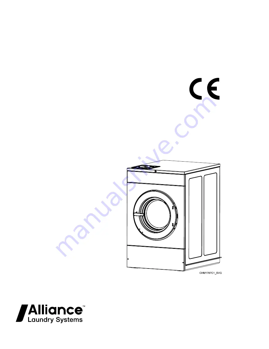
Washer-Extractors

Cabinet Hardmount

Design 4 Models

Refer to Page 8 for Model Identification

Original Instructions
Keep These Instructions for Future Reference.
CAUTION: Read the instructions before using the machine.

(If this machine changes ownership, this manual must accompany machine.)

www.alliancelaundry.com

Part No. F8619501ENR4

August 2018

Summary of Contents for UCT020 series

Page 1: ...efer to Page 8 for Model Identification Original Instructions Keep These Instructions for Future Reference CAUTION Read the instructions before using the machine If this machine changes ownership this...

Page 2: ......

Page 3: ...1 Elevated Base Frame Installation on Existing Floor 41 New Foundation 41 Isolated Pad Installation 41 Foundation and Pad Installation 42 Floor Layout and Pad Dimensions 43 Foundation Requirements 52...

Page 4: ...SCU UCA UCD UCG UCH UCJ UCT and UCU Models with N Control 97 HCA HCD HCG HCH HCJ HCT and HCU UCA UCD UCG UCH UCJ UCT and UCU Models with Q Control 97 Vend Control Instructions 99 HCT Models with N an...

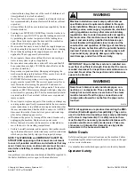
Page 5: ...must be installed to provide a separation distance of at least 20cm from all person and not be co located with any other transmitters except in accord ance with FCC and Industry Canada multi transmit...

Page 6: ...s cooking oils vegetable oils machine oils dry clean ing solvents flammable chemicals thinners or other flamma ble or explosive substances These substances give off vapors that could ignite explode or...

Page 7: ...nufacturer s instructions may result in conditions which can produce bodily injury and or property damage NOTE The WARNINGS and IMPORTANT SAFETY IN STRUCTIONS appearing in this manual are not meant to...

Page 8: ...ore starting operation of the ma chine a Attempt to start the machine with the door open The ma chine should not start b Close the door without locking it and start the machine The machine should not...

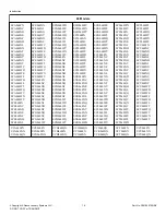
Page 9: ...NV HCG020NX HCG020NY HCG020QN HCG020WC HCG020WD HCG020WE HCG020WF HCG020WH HCG020WL HCG020WT HCG020WV HCG020WX HCG020WY HCH020FN HCH020NC HCH020ND HCH020NE HCH020NF HCH020NH HCH020NL HCH020NQ HCH020NT...

Page 10: ...SCJ020WH SCJ020WL SCJ020WQ SCJ020WT SCJ020WV SCJ020WX SCJ020WY SCK020FN SCK020NC SCK020ND SCK020NE SCK020NF SCK020NH SCK020NL SCK020NN SCK020NQ SCK020NT SCK020NV SCK020NX SCK020NY SCK020WC SCK020WD S...

Page 11: ...D HCG030WE HCG030WF HCG030WH HCG030WL HCG030WT HCG030WV HCG030WX HCG030WY HCH030FN HCH030NC HCH030ND HCH030NE HCH030NF HCH030NH HCH030NL HCH030NQ HCH030NT HCH030NV HCH030NX HCH030NY HCH030QN HCH030WC...

Page 12: ...SCJ030WH SCJ030WL SCJ030WQ SCJ030WT SCJ030WV SCJ030WX SCJ030WY SCK030FN SCK030NC SCK030ND SCK030NE SCK030NF SCK030NH SCK030NL SCK030NN SCK030NQ SCK030NT SCK030NV SCK030NX SCK030NY SCK030WC SCK030WD S...

Page 13: ...E HCH040NF HCH040NH HCH040NL HCH040NQ HCH040NT HCH040NV HCH040NX HCH040NY HCH040QN HCH040WC HCH040WD HCH040WE HCH040WF HCH040WH HCH040WL HCH040WQ HCH040WT HCH040WV HCH040WX HCH040WY HCJ040FN HCJ040NC...

Page 14: ...040NE SCK040NF SCK040NH SCK040NL SCK040NN SCK040NQ SCK040NT SCK040NV SCK040NX SCK040NY SCK040WC SCK040WD SCK040WE SCK040WF SCK040WH SCK040WL SCK040WQ SCK040WT SCK040WV SCK040WX SCK040WY SCL040FN SCL04...

Page 15: ...E HCH060NF HCH060NH HCH060NL HCH060NQ HCH060NT HCH060NV HCH060NX HCH060NY HCH060QN HCH060WC HCH060WD HCH060WE HCH060WF HCH060WH HCH060WL HCH060WQ HCH060WT HCH060WV HCH060WX HCH060WY HCJ060FN HCJ060NC...

Page 16: ...060NE SCK060NF SCK060NH SCK060NL SCK060NN SCK060NQ SCK060NT SCK060NV SCK060NX SCK060NY SCK060WC SCK060WD SCK060WE SCK060WF SCK060WH SCK060WL SCK060WQ SCK060WT SCK060WV SCK060WX SCK060WY SCL060FN SCL06...

Page 17: ...D HCU080WE HCU080WF HCU080WH HCU080WL HCU080WQ HCU080WT HCU080WV HCU080WX HCU080WY SCA080FN SCA080NC SCA080ND SCA080NE SCA080NF SCA080NH SCA080NL SCA080NN SCA080NT SCA080NQ SCA080NV SCA080NX SCA080NY...

Page 18: ...UCG080NN UCG080QN UCH080FN UCH080NN UCH080QN UCJ080FN UCJ080NN UCJ080QN UCK080NN UCK080QN UCT080FN UCT080NN UCT080QN UCU080FN UCU080NN UCU080QN Introduction Copyright Alliance Laundry Systems LLC DO...

Page 19: ...WD HCU100WE HCU100WF HCU100WH HCU100WL HCU100WQ HCU100WT HCU100WV HCU100WX HCU100WY SCA100FN SCA100NC SCA100ND SCA100NE SCA100NF SCA100NH SCA100NL SCA100NN SCA100NT SCA100NQ SCA100NV SCA100NX SCA100NY...

Page 20: ...N UCG100NN UCG100QN UCH100FN UCH100NN UCH100QN UCJ100FN UCJ100NN UCJ100QN UCK100NN UCK100QN UCT100FN UCT100NN UCT100QN UCU100FN UCU100NN UCU100QN Introduction Copyright Alliance Laundry Systems LLC DO...

Page 21: ...or Frame Figure 1 Replacement Parts If literature or replacement parts are required contact the source from which the machine was purchased or contact Alliance Laun dry Systems at 1 920 748 3950 for t...

Page 22: ...8 2 20 105 2 97 112 3 17 Slat crate shipping dimensions WxDxH in mm 32 5 x 36 8 x 55 826 x 935 x 1397 36 0 x 41 3 x 55 0 914 x 1049 x 1397 37 0 x 45 9 x 55 0 940 x 1166 x 1397 42 0 x 49 9 x 64 0 1067...

Page 23: ...extract RPM G 648 125 606 125 579 125 542 125 495 125 495 125 Very high extract RPM G 710 150 664 150 635 150 594 150 542 150 542 150 Ultra high extract RPM G 819 200 766 200 733 200 686 200 626 200...

Page 24: ...3 3 6 6 6 6 Electrical heat element size kW 2 6 2 6 2 6 2 6 4 2 4 2 Time required to raise bath temperature minutes per 10 F 5 5 C LOW 1 690 2 545 1 792 2 648 2 101 2 436 MED 2 048 3 119 2 187 2 902...

Page 25: ...Machine Dimensions Front View CHM2563N_SVG Figure 2 Specifications and Dimensions Copyright Alliance Laundry Systems LLC DO NOT COPY or TRANSMIT 25 Part No F8619501ENR4...

Page 26: ...30 9 785 30 9 785 C 17 0 432 17 0 432 17 7 450 18 1 460 21 7 551 21 7 551 D 14 4 366 14 0 356 14 6 371 14 9 378 17 9 378 17 9 378 E 26 0 660 29 0 737 30 6 777 34 1 866 41 5 1054 41 5 1054 F 1 1 28 1...

Page 27: ...Side View CHM2564N_SVG Figure 3 Specifications and Dimensions Copyright Alliance Laundry Systems LLC DO NOT COPY or TRANSMIT 27 Part No F8619501ENR4...

Page 28: ...7 3 693 31 8 808 37 0 940 39 5 1003 44 1 1120 48 1 1222 D 30 9 785 35 3 897 42 3 1074 44 7 1135 47 1 1196 51 1 1298 E 9 3 236 9 3 236 9 3 236 9 3 236 9 3 236 9 3 236 Door width 16 75 426 19 38 492 21...

Page 29: ...ical 3 7 8 Electrical 4 7 8 Electrical 5 Compartment Cold Fill Valve 6 Compartment Hot Fill Valve 7 Cold Hard Water Valve or 3rd Water Inlet 8 Pump Drain View Figure 4 Specifications and Dimensions Co...

Page 30: ...960 D 33 8 859 35 8 909 E 3 9 99 4 3 109 F 7 8 198 9 3 236 G 2 0 51 2 0 51 H 18 1 460 21 1 536 J 20 7 526 23 7 602 K 23 1 587 26 1 663 L 39 4 1001 41 4 1052 M 35 6 904 37 5 953 Table 4 Specifications...

Page 31: ...7 8 Electrical 4 7 8 Electrical 5 Steam Valve 6 Compartment Cold Fill Valve 7 Compartment Hot Fill Valve 8 Cold Hard Water Valve or 3rd Water Inlet 9 Pump Drain View Figure 5 Specifications and Dimens...

Page 32: ...1067 C 40 3 1024 D 38 0 965 E 4 5 114 F 8 8 224 G 17 0 432 H 2 0 51 J 22 8 579 K 25 4 645 L 27 7 704 M 39 7 1008 N 43 6 1107 P 39 7 1008 Table 5 Specifications and Dimensions Copyright Alliance Laundr...

Page 33: ...ical 4 7 8 Electrical 5 Tub Cold Fill Valve 6 Tub Hot Fill Valve 7 Steam Valve 8 Compartment Cold Fill Valve 9 Compartment Hot Fill Valve 10 Cold Hard Water Valve or 3rd Water Inlet Figure 6 Specifica...

Page 34: ...28 8 732 28 8 732 H 2 0 51 2 0 51 2 0 51 J 21 0 533 28 4 721 28 4 721 K 22 5 572 29 9 759 29 9 759 L 26 2 665 33 6 853 33 6 853 M 28 8 732 36 2 919 36 2 919 N 31 2 792 38 6 980 38 6 980 P 46 3 1176 52...

Page 35: ...to Table 7 CHM2609N_SVG Q L P O N M K J I F G H E C B D A S 2 1 R 3 1 Elevated Base Width 2 Front of Mounting Bolt Template 3 Machine Width Figure 7 Specifications and Dimensions Copyright Alliance La...

Page 36: ...12 28 1 033 26 G 2 15 55 1 81 46 H 2 71 69 2 37 60 I 2 8 71 2 813 71 J 4 5 114 4 51 114 K 9 638 245 10 5 267 L 20 649 525 23 5 597 M 0 113 3 0 188 5 N 23 938 608 28 938 735 O 24 69 627 29 69 754 P 27...

Page 37: ...Models 40 and 60 Models refer to Table 8 1 Elevated Base Width 2 Front of Mounting Bolt Template 3 Machine Width Figure 8 Specifications and Dimensions Copyright Alliance Laundry Systems LLC DO NOT CO...

Page 38: ...11 0 614 16 G 1 98 50 1 75 44 H 2 37 60 2 37 60 I 3 1 79 3 28 83 J 4 63 118 4 96 126 K 12 5 318 11 927 303 L 23 626 600 27 5 699 M 1 187 30 1 25 32 N 32 5 826 36 914 O 33 54 852 36 87 699 P 37 36 949...

Page 39: ...chines installed back to back use the outside bolt holes marked A For multiple machines installed side by side with minimum clearance use the inside bolt holes marked B 1 Front of Mounting Bolt Templa...

Page 40: ...0 508 13 I 1 96 50 1 96 50 J 3 38 86 3 38 86 K 0 94 24 0 94 24 L 16 406 16 406 M 35 889 35 889 N 37 28 947 37 28 947 O 42 16 1071 42 16 1071 P 49 54 1258 49 54 1258 Q 4 102 4 102 AA Outside 42 72 1085...

Page 41: ...quirements and an elevated pad is NOT desired re fer to Figure 18 and proceed to Machine Mounting and Grouting If the floor does not meet these requirements and an elevated pad is NOT desired refer to...

Page 42: ...ting floor 3 If installing a foundation with elevated pad prepare a form for the above ground portion of the foundation Verify that the top of the foundation is level The height of the foundation pad...

Page 43: ...Machine Mount 20 60 Pound 9 1 27 2 Kg Models in mm Description 20 30 40 60 A Distance to wall minimum 24 610 24 610 24 610 24 610 B Distance of machine base to edge of pad minimum 3 44 87 4 102 3 99...

Page 44: ...1 27 2 Kg Models refer to Table 12 CHM2505N_SVG C D 1 2 E 3 5 2 4 5 A B B 1 Wall 2 Rear Edge of Pad 3 Machine 1 4 Machine 2 5 Front Edge of Pad Figure 12 Dimensional Clearances Side by Side Mount 20 6...

Page 45: ...06 103 Mounted with bases mini mum 5 5 139 5 5 139 4 88 124 4 44 112 C Length of pad minimum 34 8 884 39 5 1003 43 5 1105 50 6 1285 D Width of pad minimum 57 54 1462 63 52 1613 67 38 1711 78 98 2006...

Page 46: ...nal Clearances Back to Back Mount 20 60 Pound 9 1 27 2 Kg Models in mm Description 20 30 40 60 A Adjacent rear bolt spacing minimum 28 3 719 27 6 702 28 0 710 27 5 699 B Distance from front bolt to ed...

Page 47: ...927 44 8 1138 Table 13 Dimensional Clearances Single Machine Mount 80 and 100 Pound 36 3 and 45 4 Kg Models refer to Table 14 CHM2519N_SVG D E 1 2 3 4 5 A C C B B 1 Wall 2 Rear Edge of Pad 3 Side Edge...

Page 48: ...minimum 24 610 B Distance of machine base to edge of pad minimum 4 98 126 C Distance of machine base to edge of pad minimum 8 203 D Length of pad minimum 49 2 1250 E Width of pad minimum 57 5 1461 Tab...

Page 49: ...hine 2 5 Front Edge of Pad Figure 15 Standard Mount Side by Side 80 and 100 Pound 36 3 and 45 4 Kg Models in mm Description 80 100 A Distance to wall minimum 24 610 B Adjacent unit spacing minimum 6 1...

Page 50: ...6 3 and 45 4 Kg Models in mm Description 80 100 A Distance to wall minimum 24 610 B Adjacent unit bolt spacing minimum 10 38 264 C Length of pad minimum 49 2 1250 D Width of pad minimum 99 5 2527 IMPO...

Page 51: ...t facing Edge of Pad 2 Machine 2 3 Rear of Machine 4 Machine 1 5 Side Edge of Pad or Wall Figure 17 Back to Back Mount 80 and 100 Pound 36 3 and 45 4 Kg Models in mm Description 80 100 A Adjacent rear...

Page 52: ...5 1308 Table 17 Pad Thickness Requirements in mm Specification 20 30 40 60 80 100 Minimum Foun dation Thickness F speed 4 102 4 102 4 102 4 102 6 152 V speed 4 102 4 102 6 152 6 152 9 229 Minimum Exca...

Page 53: ...0 40 60 F speed 40 60 V speed 80 100 F speed 80 100 V speed A Required thickness of existing floor minimum 4 102 4 102 6 152 9 229 Table 19 New Monolithic Floor refer to Table 20 PHM981N_SVG 2 3 B A 1...

Page 54: ...F speed 80 100 V speed A Depth of Surrounding Floor 4 102 4 102 6 152 6 152 B Total depth of foundation con crete plus 6 in 152 mm fill minimum 8 203 8 203 12 305 15 381 Table 20 Installation Copyrig...

Page 55: ...t of elevated pad above floor maximum 8 203 8 203 8 203 8 203 B Distance between reinforcing bars maximum 12 305 12 305 12 305 12 305 C Length of reinforcing bar ex tending into existing floor mini mu...

Page 56: ...V speed 80 100 F speed 80 100 V speed A Required thickness of existing floor minimum 4 102 4 102 6 152 6 152 B Total depth of foundation con crete plus 6 in 152 mm fill minimum 8 203 8 203 12 305 15...

Page 57: ...il all voids are filled IMPORTANT Minimum Grade 5 SAE rating flat washers and minimum Grade 5 SAE rating serrated hex flange locknuts are the recommended hardware for anchoring machine or elevated bas...

Page 58: ...hine Frame Base 2 Grout 1 2 in 13 mm 3 Acrylic Adhesive 4 Anchor Bolt minimum Grade 5 SAE rating 5 Concrete 6 Drill Hole Size per Manufacturer Requirements 7 Edge of Pad Figure 22 Cast in place Anchor...

Page 59: ...0 40 60 80 100 Static floor load lbs kN 430 1 91 550 2 45 690 3 07 920 4 09 1590 7 07 1690 7 51 Static pressure lbs ft2 kN m2 97 4 64 95 4 55 98 4 69 105 5 03 140 6 70 149 7 13 Dynamic floor load lbs...

Page 60: ...to the 3 inches 76 mm schedule 40 PVC plumbing If proper drain size is not available or practical a surge tank is required A surge tank along with a sump pump should be used when gravity drainage is...

Page 61: ...ation Specification 20 30 40 60 80 100 Drain connection size in 3 3 3 3 3 3 Overflow drain connection size in 1 1 2 2 1 4 2 1 4 2 1 4 2 1 4 2 1 4 Number of drain outlets 1 1 1 1 1 1 Drain flow capacit...

Page 62: ...roportionately larger water lines Connections should be supplied by a hot and a cold water line per national and local codes and in accordance with AS NZS 3500 I Water Supply Information Specification...

Page 63: ...um inlet di mension of 1 2 inch ID NOTE This machine has a fluid category 5 backflow prevention device built in between the soap tray and drum PHM831N_SVG 4 5 3 2 1 1 Air Cushions Risers 2 Water Suppl...

Page 64: ...arked with a red label Screw the coupling with the plain rubber washer of the blue color coded hose at tached to the cold water connection to the valve inlet marked with a blue label Tighten to finger...

Page 65: ...the tub fill valve inlet marked with a red label Tighten to finger tight Refer to Figure 30 8 Screw the coupling with the plain rubber washer of one 1 of the blue color coded hoses attached to the co...

Page 66: ...Plumbing Diagrams 20 60 Models Side View refer to Table 28 Figure 31 Installation Copyright Alliance Laundry Systems LLC DO NOT COPY or TRANSMIT 66 Part No F8619501ENR4...

Page 67: ...20 60 Models Rear View refer to Table 28 CHM2641N_SVG 1 Vacuum Breaker Overflow Figure 32 Installation Copyright Alliance Laundry Systems LLC DO NOT COPY or TRANSMIT 67 Part No F8619501ENR4...

Page 68: ...operating water level 18 5 470 17 0 432 19 9 505 C Vaccum breaker overflow 33 9 861 35 8 909 38 0 965 D Vaccum breaker overflow centerline 35 5 902 37 5 953 39 7 1008 E Inlet Valves 38 9 988 41 4 1052...

Page 69: ...60 100 Models Side View refer to Table 29 Figure 33 Installation Copyright Alliance Laundry Systems LLC DO NOT COPY or TRANSMIT 69 Part No F8619501ENR4...

Page 70: ...60 100 Models Rear View refer to Table 29 1 1 Vacuum Breaker Overflow Figure 34 Installation Copyright Alliance Laundry Systems LLC DO NOT COPY or TRANSMIT 70 Part No F8619501ENR4...

Page 71: ...ARNING Hazardous Voltage Can cause shock burn or death Verify that a ground wire from a proven earth ground is connected to the lug near the input power block on this machine W360 WARNING This Machine...

Page 72: ...ents For voltages above or below listed specifications contact your power company or local electrician IMPORTANT Improper connections will result in equip ment damage and will void warranty DANGER Ele...

Page 73: ...22 2 or 3 5 mm gap is required to meet Standard IEC 60335 1 clauses 24 3 and 22 2 Gap is defined as the minimum contact sepa ration of each pole in the switch between the ON and OFF positions Single P...

Page 74: ...pipes WARNING Electrically heated machines DO NOT require dual power sources Do not connect customer power or customer load to the Internal Load Distribution ter minal block Refer to the machine elec...

Page 75: ...Specifications Code Voltage Cycle Phase Wire Full Load Amps Circuit Breaker AWG mm 2 F Speed Models B 120 60 1 2 8 15 14 2 5 W 200 240 50 1 3 2 3 4 3 15 14 2 5 Y 200 240 60 1 3 2 3 4 3 15 14 2 5 X 20...

Page 76: ...ifications Code Voltage Cycle Phase Wire Full Load Amps Circuit Breaker AWG mm 2 N Standard 440 480 50 60 3 3 2 15 14 2 5 Electric Heat 14 15 14 2 5 Table 31 Installation Copyright Alliance Laundry Sy...

Page 77: ...rd 380 415 50 60 3 3 3 15 14 2 5 Electric Heat 12 15 14 2 5 N 440 480 50 60 3 3 3 15 14 2 5 14 15 14 2 5 V Speed Models B 120 60 1 2 12 15 12 4 W 200 240 50 1 3 2 3 7 4 15 14 2 5 Y 200 240 60 1 3 2 3...

Page 78: ...0 60 3 3 3 15 14 2 5 Electric Heat 24 30 10 6 0 N Standard 440 480 50 60 3 3 3 15 14 2 5 Electric Heat 22 30 10 6 0 V Speed Models B 120 60 1 2 12 15 12 2 5 W 200 240 50 1 2 3 7 4 15 14 2 5 Y 200 240...

Page 79: ...60 3 3 4 15 14 2 5 Electric Heat 26 30 10 6 0 N Standard 440 480 50 60 3 3 4 15 14 2 5 Electric Heat 22 30 10 6 0 V Speed Models X 200 240 50 60 1 3 2 3 11 7 15 14 2 5 Q Electric Heat 200 240 50 60 3...

Page 80: ...3 3 5 15 14 2 5 Electric Heat 33 40 8 10 0 N Standard 440 480 50 60 3 3 5 15 14 2 5 Electric Heat 36 40 8 10 0 V Speed Models X 200 240 50 60 1 3 2 3 15 9 20 15 12 14 4 2 5 Q Electric Heat 200 240 50...

Page 81: ...3 3 5 15 14 2 5 Electric Heat 32 40 8 10 0 N Standard 440 480 50 60 3 3 5 15 14 2 5 Electric Heat 36 40 8 10 0 V Speed Models X 200 240 50 60 1 3 2 3 16 10 20 15 12 14 4 2 5 Q Electric Heat 200 240 50...

Page 82: ...sectional area shall be provided up to a point where the protective conductor has a cross sectional area not less than 10 mm2 Cu 20 Models CE Approval Voltage Designation Specifications Code Voltage C...

Page 83: ...17 20 25 2 5 P Standard 380 415 50 60 3 3 3 6 2 5 Electric Heat 11 16 2 5 N 440 480 50 60 3 3 3 6 2 5 V Speed Models B 120 60 1 2 12 16 2 5 W 200 240 50 1 3 2 3 7 4 10 6 2 5 Y 200 240 60 1 3 2 3 7 4...

Page 84: ...50 60 3 3 3 6 2 5 Electric Heat 23 25 2 5 N Standard 440 480 50 60 3 3 3 6 2 5 Electric Heat 20 25 2 5 V Speed Models B 120 60 1 2 12 16 2 5 W 200 240 50 1 3 2 3 7 4 10 6 2 5 Y 200 240 60 1 3 2 3 7 4...

Page 85: ...80 415 50 60 3 3 4 6 2 5 Electric Heat 23 32 2 5 N Standard 440 480 50 60 3 3 4 6 2 5 Electric Heat 20 25 2 5 V Speed Models X 200 240 50 60 1 3 2 3 11 7 16 10 2 5 Q Electric Heat 200 240 50 60 3 3 33...

Page 86: ...15 50 60 3 3 5 6 2 5 Electric Heat 30 40 4 0 N Standard 440 480 50 60 3 3 5 6 2 5 Electric Heat 35 40 4 0 V Speed Models X 200 240 50 60 1 3 2 3 17 11 20 16 2 5 Q Electric Heat 200 240 50 60 3 3 59 70...

Page 87: ...15 50 60 3 3 5 6 2 5 Electric Heat 30 40 4 0 N Standard 440 480 50 60 3 3 5 6 2 5 Electric Heat 35 40 4 0 V Speed Models X 200 240 50 60 1 3 2 3 17 11 20 16 2 5 Q Electric Heat 220 240 50 60 3 3 59 70...

Page 88: ...e machine and void the warranty The chemical supply connector is located on the back right hand side of the machine There are 12 chemical ports on the connec tor through each a liquid supply hose can...

Page 89: ...Figure 42 for detail of chemical supply connector C CHM1N1_SVG1 1 Chemical Supply Connector 2 External Liquid Supply Connection Ports 12 Figure 41 Installation Copyright Alliance Laundry Systems LLC D...

Page 90: ...A flush manifold system can only be connected through the top 6 ports boxed 1 3 4 inch port O D 2 1 2 inch port O D 3 3 8 inch port O D Figure 42 Installation Copyright Alliance Laundry Systems LLC DO...

Page 91: ...available but require some wiring changes and must be provided with an external power source Under no circumstances should the high voltage machine supply connections or source be used for the commun...

Page 92: ...l supplies must not be derived from the high voltage main power connection point IMPORTANT The external power must supply power of 240VAC or less and be protected at 3 Amps or less 1 Disconnect and ca...

Page 93: ...gnal board if ES1 is selected the K1 contact will close and power will be supplied to Supply 1 Signal The contact will remain closed for the amount of time programmed in control Refer to Figure 48 for...

Page 94: ...supply 2 K12 Contact 3 Supply 1 Signal Figure 50 1 ES1 Power supply 2 K12 Contact 3 Supply 1 Signal Figure 51 Installation Copyright Alliance Laundry Systems LLC DO NOT COPY or TRANSMIT 94 Part No F8...

Page 95: ...ck that basket rotation is counter clockwise in the ex tract step 1 If rotation is not counter clockwise disconnect power to ma chine 2 Have a qualified electrician reverse any two motor leads at the...

Page 96: ...nets to prevent drain blockage IMPORTANT To prevent out of balance conditions premature wear or damage to machine when using laundry nets use several small nets in a load 4 Close the door and turn han...

Page 97: ...H SCJ SCT SCU UCA UCD UCG UCH UCJ UCT and UCU Models with N Con trol Figure 56 1 If equipped with an optional supply dispenser add dry sup plies to the compartment cups prior to the start of each cycl...

Page 98: ...Refer to Table 44 a Detergent Liquid Compartment 1 prewash Compartment 3 Powder Compartment 1 prewash Compartment 2 b Bleach Liquid Compartment 3 Powder Compartment 2 c Softener Liquid Compartment 4 3...

Page 99: ...When a cycle is complete the control displays OPEN DOOR SCA SCE SCG SCJ and SCU Models with N and W Controls Figure 59 1 Press the Normal 90C Normal 60C Normal 40C Perminant Press 60C Delecates 30C o...

Page 100: ...unit insert and remove card per card system instructions If the unit is interfaced to a central remote pay system go to the central remote pay console make payment and se lect the machine and follow c...

Page 101: ...ard operated unit insert and remove card per card system instructions If the unit is interfaced to a central remote pay system go to the central remote pay console make payment and se lect the machine...

Page 102: ...h Spin Door Hot Warm Cold Heavy Hot Quick Hot Delicate Warm Delicate Cold START Quick Warm Figure 63 1 Press the Hot Warm Cold Heavy Hot Delicate Warm Deli cate Cold Quick Hot or Quick Warm keypad to...

Page 103: ...nt CHM2227N_SVG 2 2 Powder Detergent b BLEACH CHM2229N_SVG 3 3 Liquid Bleach CHM2230N_SVG 4 4 Powder Bleach c SOFTENER CHM2231N_SVG 5 5 Liquid Softener Table 44 Operation Copyright Alliance Laundry Sy...

Page 104: ...n Figure 64 1 Press red emergency stop button to stop all action 2 To restart the machine pull red emergency stop button out and press START enter on the control Operation Copyright Alliance Laundry S...

Page 105: ...and functioning properly 3 Inspect water inlet valve hose connections on the back of the machine for leaks 4 Inspect steam hose connections for leaks if applicable 5 On machines equipped with an autom...

Page 106: ...ting Anti oxidizing Mechanically stable The grease must have adequate base oil viscosity with one of the following ratings ISO VG 150 709 871 SUS at 100 F 135 165 cSt at 40 C ISO VG 220 1047 1283 SUS...

Page 107: ...ley Belt Tension by Frequency or Belt Tension Gauge Model Frequen cy Hz Belt Ten sion lbs Tension Gauge N 20 88 2 60 4 6 1 269 27 30 84 2 63 2 6 3 281 28 40 75 2 88 6 8 8 394 39 60 70 2 100 2 5 7 446...

Page 108: ...similar metals to prevent galvanic cor rosion when salty or acidic solutions are present Do not allow salty or acidic solutions to evaporate and dry on stainless steel Wipe clean of any residues Rub i...

Page 109: ...nt En suring this product is disposed of correctly will help prevent po tential negative consequences for the environment and human health which could otherwise be caused by inappropriate waste handli...

Page 110: ...able is prepared in accordance with the provisions of SJ T 11364 O Indicates that the content of said hazardous substance in all of the homogenous materials in the component is within the limits requi...

Reviews: