PHM963N_SVG
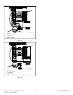
1
2
5
4
3
1.
Top Nut
2.
Jam Nut
3.
Spring Length
4.
Spring
5.
Eyebolt
Figure 66
•
Tension Gauge.
Tighten eyebolt top nut until the prop-
er belt gauge (refer to
Table 8
) is obtained mid-span.
Torque jam nut to spring bracket to 20.6 ± 2 ft.-lbs.
Refer to
Figure 66
.
•
Spring Length.
Tighten eyebolt top nut until the
spring measures the correct distance between the
hooks. Refer to
Table 45
. Torque jam nut to spring
bracket to 20.6 ± 2 ft.-lbs. Refer to
Figure 66
.
Spring Length, in. [mm]
Model
Distance Between
Hooks
20 (2 HP)
4-9/16 [116]
30
4-1/2 [114]
40
4-5/8 [117]
60
5-1/4 [133]
80
4-9/16 [116]
100
4-9/10 [124]
Table 45
•
Maintain Tension During Belt Removal.
If proper
tension is achieved, tape the jam nut in place and loos-
en eyebolt top nut to release the belt. Replace belt and
retighten eyebolt top nut back to jam nut position. Re-
fer to
Figure 66
.
IMPORTANT: All torque joints must remain dry
(non-lubricated).
b.
20-60 Models:
verify the belt is centered on the basket
pulley with in one (1) rib.
80-100 Models:
verify the belt
is within the allowable distance of .04 inch [1 mm] be-
tween the belt and the edge of basket pulley.
Belt Tension by Frequency or Belt Tension
Gauge
Model
Frequen-
cy (Hz)
Belt Ten-
sion
(lbs.)
Tension
Gauge
(N)
20
88 ± 2
60.4 ± 6.1
269 ± 27
30
84 ± 2
63.2 ± 6.3
281 ± 28
40
75 ± 2
88.6 ± 8.8
394 ± 39
60
70 ± 2
100.2 ± 5.7
446 ± 25
80
102 ± 2
135 ± 5
601 ± 23
100
110 ± 2
158 ± 5
702 ± 23
Table 46
3. Remove any accumulated debris on or near the motor and
motor variable frequency drive heat sinks, if applicable.
4. If applicable, unlock or unscrew the top cover and inspect the
supply dispenser hoses and hose connections for visible signs
of deterioration. Replace hoses if worn or damaged.
NOTE: Hoses and other natural rubber parts deterio-
rate after extended use. Hoses may develop cracks,
blisters or material wear from the temperature and
constant high pressure they are subjected to.
5. Remove any dust from all electrical components, including
coin acceptors if applicable, with compressed air.
6. Inspect hardware for any loose nuts, bolts, screws.
a. Check the tightness of the motor spring and motor pulley
hardware. Also check that the eyebolt is tightened proper-
ly.
b. Tighten motor mounting bolt locknuts and bearing bolt
locknuts, if necessary.
c. Check the bearing mounting bolts to make sure they are
torqued properly. Refer to
Table 47
.
Maintenance
©
Copyright, Alliance Laundry Systems LLC -
DO NOT COPY or TRANSMIT
107
Part No. F8619501ENR4
Summary of Contents for UCT020 series
Page 2: ......


