background image

Installation/Maintenance

Washer-Extractor

Cabinet Freestanding

Model Numbers

BF35PV

SF35PV

UF35PV

BF50PV

SF50PV

UF50PV

BF85PV

SF85PV

UF85PV

NOTA: El manual en 
español aparece después

del manual en inglés.

Part No. F232058R5

November 1999

Summary of Contents for UF35PV

Page 1: ...tenance Washer Extractor Cabinet Freestanding Model Numbers BF35PV SF35PV UF35PV BF50PV SF50PV UF50PV BF85PV SF85PV UF85PV NOTA El manual en espa ol aparece despu s del manual en ingl s Part No F23205...

Page 2: ......

Page 3: ...mensional Clearances 14 Machine Foundation 18 Mechanical Installation 19 Mounting Bolt Installation for 35 Pound 50 Pound and 85 Pound Capacity Models 19 Drain Connection 23 Water Connection 25 Electr...

Page 4: ...yright 1999 Alliance Laundry Systems LLC All rights reserved No part of the contents of this book may be reproduced or transmitted in any form or by any means without the expressed written consent of...

Page 5: ...terminals Only qualified personnel familiar with electrical test procedures test equipment and safety precautions should attempt adjustments and troubleshooting Disconnect power from the machine befor...

Page 6: ...arning symbol indicates the presence of hot surfaces that could cause serious burns Stainless steel and steam lines can become extremely hot and should not be touched This warning symbol indicates the...

Page 7: ...oor without locking it and attempt to start the machine The machine should not start with the door unlocked c Close and lock the door and start a cycle Attempt to open the door while the cycle is in p...

Page 8: ...use safety hazards external to the machine in conjunction with adjacent electrical equipment Ventilation The need for make up air openings for such laundry room accessories as dryers ironers water hea...

Page 9: ...use personal injury For machines equipped with optional steam heat install piping in accordance with approved commercial steam practices Failure to install the supplied steam filter may void the warra...

Page 10: ...the power supply can cause the AC inverter drive to generate nuisance errors If voltage is above 230V for 200V installations or above 440V for 400V installations a buckboost transformer is recommended...

Page 11: ...ultra high extract speeds The cylinder is supported by roller bearings housed inside a trunnion The cylinder is constructed with four lifters or ribs that lift the laundry from the bath solution when...

Page 12: ...of possible damage are evident have the carrier note the condition on the shipping papers before the shipping receipt is signed or advise the carrier of the condition as soon as it is discovered Remov...

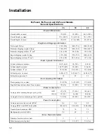
Page 13: ...Capacity pounds dry weight P Type of Electrical Control P WE 6 Computer V Machine Speed Capabilities V 7 Speeds Q Electrical Characteristics See Voltage Designation Chart in this section U3 Design Se...

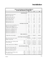
Page 14: ...668 30 762 36 914 Cylinder depth in mm 18 375 467 20 508 24 610 Cylinder volume ft3 l 5 79 164 8 19 232 14 1 400 Perforation size in mm 0 188 4 77 0 188 4 77 0 188 4 77 Perforation open area 23 23 23...

Page 15: ...extract 3 centrifugal force Gs 345 345 348 Balance Detection Vibration safety switch installed Standard Standard Standard Direct Steam Heating Optional Steam inlet connection size in mm 0 5 DN15 0 5...

Page 16: ...ons shown here are for planning purposes only They are approximate and subject to normal manufacturing tolerances If exact dimensions are required for construction purposes contact the distributor or...

Page 17: ...IE3B 32 814 mm 25 1 10 638 mm 22 559 mm 35 889 mm 39 992 mm 32 3 5 828 mm 32 813 mm 23 9 10 606 mm 49 2 5 1255 mm 40 3 5 1031 mm 11 4 5 300 mm 8 1 5 209 mm 11 279 mm 52 1 10 1323 mm 55 2 5 1408 mm 35...

Page 18: ...B 34 3 10 872 mm 26 1 5 666 mm 22 9 10 582 mm 39 991 mm 41 3 10 1049 mm 36 3 5 930 mm 35 889 mm 24 2 5 619 mm 44 7 10 1136 mm 11 4 5 300 mm 10 1 5 260 mm 10 1 5 260 mm 55 1 10 1399 mm 59 3 5 1513 mm 5...

Page 19: ...32 7 10 831 mm 30 1 10 765 mm 46 1 2 1181 mm 43 3 5 1107 mm 42 3 5 1083 mm 29 9 10 758 mm 25 2 5 645 mm 70 1 10 1781 mm 66 2 5 1685 mm 7 3 4 197 mm 11 1 10 281 mm 50 3 5 1284 mm 51 3 5 1311 mm 10 254...

Page 20: ...state or local codes Static and dynamic loads on the floor or foundation are shown in the table below This table can be used as a reference when designing floors and foundations Ensure that the machi...

Page 21: ...nd capacity models The front of the washer extractor is the bottom of the diagram See Figure 8 for detailed information regarding the machine anchor bolt that should be used Figure 5 Figure 6 Figure 7...

Page 22: ...he washer extractor carefully over the anchor bolts Never attempt to lift the machine by the door handle or by pushing on the cover panels 4 Raise and level the washer extractor 1 2 inch off the floor...

Page 23: ...d locknuts on the anchor bolts and fingertighten locknuts to machine base 8 After the grout is completely dry tighten the locknuts by even increments one after the other until all are tightened evenly...

Page 24: ...Installation 22 F232058 Figure 12 B147IE3A Rear Panel Four 4 Transport Brackets Front Panel...

Page 25: ...h as in below ground level installations Before any deviation from specified installation procedures is attempted the customer or installer should contact the distributor Increasing the drain hose len...

Page 26: ...79 3 79 Number of drain outlets 1 1 1 Drain flow capacity gal min l min 54 205 54 205 54 205 Recommended drain pit size ft3 l 5 7 161 8 2 232 10 7 303 Drain Line Sizing Minimum Drain I D in mm Model...

Page 27: ...r foreign particles out of the water inlet valves Pressure of 30 85 psi 2 5 7 bar provides best performance Although the washer extractor will function properly at lower pressures increased fill times...

Page 28: ...d personnel familiar with electrical test procedures test equipment and safety precautions should attempt adjustments and troubleshooting Disconnect power from the machine before removing the control...

Page 29: ...tional Electric Code or other applicable codes The connection must be made by a qualified electrician using the wiring diagram provided with the washer extractor or according to accepted European stan...

Page 30: ...2 19 30 10 3x6 Not available in this voltage 50 M 550 575 50 60 3 3 6 15 14 3x2 5 Not available in this voltage M 550 575 50 60 3 3 10 15 14 3x2 5 Not available in this voltage N 440 480 50 60 3 3 4 1...

Page 31: ...ed steam filter may void the warranty Never touch internal or external steam pipes connections or components These surfaces can be extremely hot and will cause severe burns The steam must be turned of...

Page 32: ...ed Failure to follow these instructions could damage the machine and void the warranty See Figure 15 for a typical chemical supply injection system Figure 15 Wear eye and hand protection when handling...

Page 33: ...hemical Injection Supply Systems A stainless steel box at the rear of the machine houses a terminal strip which furnishes supply output signals for the chemical injection supply pumps See Figure 18 fo...

Page 34: ...mpting to obtain 110VAC by using L1 or L2 with the common may damage laundry machine circuitry and or the chemical injection system Using a 240VAC power wire in the washer extractor and an earth groun...

Page 35: ...side front panel of the washer extractor 2 Building the right drain for water recirculation a Remove the drain cover plate on the right side of washer extractor rear See Figure 19 b Remove the sump p...

Page 36: ...s using the blue female quick disconnect terminals included in the kit Rear Panel 1 4 20 Fiberlock Nut 1 4 20 x 5 8 Screw Recirculation Adapter Plate 1 4 20 Fiberlock Nut 1 4 20 Fiberlock Nut 1 4 20 x...

Page 37: ...e the cover on the rear control module by removing the screws On newer models the cover is removed by using a key originally shipped with the machine b On the 35 and 50 pound models attach the pump co...

Page 38: ...e the top two plugs of the three black plugs from the right side of the rear control module These plugs are located just to the right of the pump contactor and circuit breaker See Figure 21 On the 85...

Page 39: ...BLACK RED 2 conductor cable from pump motor G R E E N Y E L L O W Cut strip and crimp blue spade terminal to green yellow wire Use No 10 screw and nut provided to attach wire to AC drive module Pump...

Page 40: ...rive Box RED RED BLACK BLACK GREEN YELLOW Watertight PG 21 strain relief 2 conductor cable from pump motor thermal overload 4 conductor cable from pump motor 3 phase power AC Drive Box Cut strip and c...

Page 41: ...op Of Frame Follow Main Drive Motor Cable Route to AC Drive Module Main Drive Motor Sewer Drain Valve Main Drive Motor Sewer Drain Valve 2 Conductor Cable And 4 Conductor Cable Wet Clean Module Cable...

Page 42: ...tactor h Connect L1 L2 and L3 from the circuit breaker to the input side of the mains contactor using the 18GA gray wire included in the kit i Connect the 4 conductor cable wires to the pump contactor...

Page 43: ...1 1 2 inch black connector with clamp grooves included in the kit onto the upper recirculation pipe side of the lower recirculation pipe g Assemble the other 1 1 2 inch black connector with clamp gro...

Page 44: ...Emergency Stop button 6 Check the door interlock before starting operation a Attempt to start the washer with the door open The washer extractor should not start with the door open b Close the door w...

Page 45: ...step If rotation is not correct disconnect power A qualified electrician must reverse any two leads between the AC drive and the main drive motor See Figure 27 If the washer extractor is served by th...

Page 46: ...Clean Module pump is operating properly and that the rotation direction is counterclockwise If rotation direction is incorrect a qualified electrician may reverse any two leads See Step 6i of Premium...

Page 47: ...act on all external wires and that all connections are secure If bare wire is evident call a service technician 4 Check door interlock before starting operation a Attempt to start the washer with the...

Page 48: ...each completed cycle to prevent moisture buildup Leave loading door open at the end of each completed cycle to allow moisture to evaporate Weekly 1 Check the machine for leaks a Start an unloaded cycl...

Page 49: ...removing all panels necessary for access to the drive belt use the following method to verify that V belts are properly tensioned See Figure 28 Belt deflection should be measured as close to the cente...

Page 50: ...performing the quarterly maintenance procedures 1 Tighten door hinges and fasteners if necessary 2 Tighten anchor bolts if necessary 3 Check all painted surfaces for bare metal Matching gray paint is...

Page 51: ...on the stainless steel Use stainless steel wool or soft non metal bristle brushes If the stainless steel appears to be rusting the source of the rust may actually be an iron or steel part not made of...

Page 52: ...asher with door open b Close the door without locking it and attempt to start the washer c Close and lock the door start a cycle and attempt to open the door while the cycle is in progress 5 End of Da...

Page 53: ...__________ Operator ___________________________ Month __________ Week Ending Checks Observe All Safety Warnings 1 Check the machine for leaks a Start an unloaded cycle to fill the machine b Verify tha...

Page 54: ...ean the AC drive fins 3 Determine if V belts require replacement or adjustment a Check V belts for uneven wear and frayed edges b Verify that V belts are properly tensioned c Verify that V belts are p...

Page 55: ...performing the quarterly maintenance procedures 1 Tighten door hinges and fasteners if necessary 2 Tighten anchor bolts if necessary 3 Check all painted surfaces for bare metal Repair if necessary 4...

Page 56: ...54 NOTES F232058 Maintenance...

Page 57: ...b Do not attempt to disconnect power supply wires from power supply Have a qualified electrician disconnect power to machine at its source 4 Disconnect hoses a Disconnect drain hose from sump gutter o...

Page 58: ...issioning Continued e Use crowbars at the front corners to lift the machine a few inches so that the forks of a forklift truck can reach under the machine f Bolting the base frame to a pallet will fac...

Page 59: ...Instalaci n Mantenimiento Lavadora extractora con gabinete incorporado N meros de modelo BF35PV SF35PV UF35PV BF50PV SF50PV UF50PV BF85PV SF85PV UF85PV Pieza No F232058R5 Noviembre 1999...

Page 60: ......

Page 61: ...s para la m quina 78 Instalaci n mec nica 79 Instalaci n de los pernos de montaje para los modelos con capacidades de 35 50 y 85 libras 79 Conexi n del desag e 83 Conexi n de agua 85 Instalaci n el ct...

Page 62: ...Alliance Laundry Systems LLC Reservados todos los derechos Ninguna secci n del presente manual puede ser reproducida o transmitida en forma alguna o a trav s de ning n medio sin el expreso consentimi...

Page 63: ...tor S lo el personal capacitado para realizar procedimientos de pruebas el ctricas y conocedor del equipo de pruebas y de las precauciones de seguridad debe intentar hacer ajustes y reparar aver as De...

Page 64: ...indica que existen superficies calientes que podr an causar graves quemaduras El acero inoxidable y las l neas de vapor pueden ponerse demasiado calientes y no deben ser tocadas Este s mbolo de adver...

Page 65: ...est abierta b Cierra la puerta sin ponerle el seguro e intente arrancar la m quina La m quina no debe arrancar si la puerta no est asegurada c Cierre y ponga el seguro a la puerta y comience el ciclo...

Page 66: ...s y las mangueras de goma caucho pueden secarse Esta condici n puede ocasionar fugas en las mangueras lo que puede presentar peligros externos a la m quina y al equipo el ctrico adyacente Ventilaci n...

Page 67: ...quina pueden sufrir da os ciertos componentes pueden fallar y pueden ocasionarse graves lesiones personales Presi n de vapor opcional Se obtiene el mejor rendimiento si el vapor se suministra a una pr...

Page 68: ...uentemente el filtro del ventilador de enfriamiento del mando inversor de CA y el mando en s Las fluctuaciones de corriente el ctrica de fuentes tales como suministros de potencia no interrumpible UPS...

Page 69: ...nca lave piezas de maquinaria o de autom viles en la m quina Esto puede da ar seriamente la canasta Nunca permita que los ni os jueguen en o cerca de esta m quina Si alg n ni oqueda atrapado dentro de...

Page 70: ...68 NOTAS F232058 SP Seguridad...

Page 71: ...a velocidades programables del motor mediante un solo motor De esta manera le es posible alcanzar velocidades de extracci n sumamente altas El cilindro est soportado mediante rodamientos de bolas mont...

Page 72: ...para determinar si existen da os visibles Si la caja la cubierta o la unidad est n da adas o tienen se ales evidentes de posible da os pida al transportista que anote esta condici n en los documentos...

Page 73: ...extractora libras de peso en seco P Tipo de control el ctrico P Computadora WE 6 V Velocidades disponibles de la lavadora extractora V 7 velocidades Q Caracter sticas el ctricas Vea la tabla de espec...

Page 74: ...ilindro mm plg 467 18 375 508 20 610 24 Volumen del cilindro lt pie3 164 5 79 232 8 19 400 14 1 Tama o de las perforaciones mm plg 4 77 0 188 4 77 0 188 4 77 0 188 rea abierta de las perforaciones 23...

Page 75: ...centr fuga a velocidad alta de extracci n 3 Gs 345 345 348 Detecci n de balance Interruptor de protecci n contra vibraciones Est ndar Est ndar Est ndar Calentamiento por vapor directo opcional Tama o...

Page 76: ...dimensiones que aparecen aqu s lo son para prop sitos de planeaci n Son valores aproximados y est n sujetos a las tolerancias normales de fabricaci n Si tiene necesidad de conocer las dimensiones exa...

Page 77: ...75 Instalaci n F232058 SP Figura 2 B145IE3A Modelos de Capacidad 35 Libras Parte delantera Parte lateral Parte posterior...

Page 78: ...26 1 5 638 mm 22 9 10 599 mm 39 991mm 41 3 10 1049 mm 36 3 5 930 mm 35 889 mm 24 2 5 619 mm 44 7 10 1136 mm 11 4 5 300 mm 10 1 5 260 mm 10 1 5 260 mm 55 1 10 1399 mm 59 3 5 1513 mm Modelos de Capacid...

Page 79: ...77 Instalaci n F232058 SP Figura 4 U091I Modelos de Capacidad 85 Libras Parte delantera Parte lateral Parte posterior...

Page 80: ...e lo establezcan los c digos locales o estatales Las cargas est ticas y din micas en el piso o en los cimientos aparecen en la siguiente tabla Esta tabla puede ser usada como referencia al dise ar pis...

Page 81: ...se los diagramas de montaje de los pernos en la Figura 6 para la m quina de 50 libras de capacidad Use los diagramas de montaje de los pernos en la Figura 7 para la m quina de 85 libras de capacidad L...

Page 82: ...la manija de la puerta o empujando los paneles de la cubierta 4 Levante y nivele la lavadora extractora 1 2 pulgada sobre el piso en tres puntos utilizando espaciadores tales como tuercas 5 Rellene e...

Page 83: ...dos a la base de la m quina 8 Una vez que la lechada est completamente seca apriete las contratuercas en incrementos iguales una tras otra hasta que haya apretados todas en forma pareja y la lavadora...

Page 84: ...Instalaci n 82 F232058 SP Figura 12 B147IE3A Panel trasero Cuatro 4 soportes para transporte Panel delantero...

Page 85: ...os procedimientos especificados de instalaci n el cliente o el instalador debe ponerse en contacto con el distribuidor Al aumentar la longitud de la manguera de desag e al instalar codos o al causar c...

Page 86: ...mero de salidas de desag e 1 1 1 Capacidad de flujo del desag e l min gal min 205 54 205 54 205 54 Tama o de foso para desag e recomendado l pies3 161 5 7 232 8 2 303 10 7 Tama o de l nea de desag e D...

Page 87: ...do para evitar que la corrosi n y las part culas extra as entren a las v lvulas de entrada de agua Una presi n de agua entre 2 y 5 7 Barias 30 y 85 PSI ofrece el mejor rendimiento Aunque la lavadora e...

Page 88: ...quipo y puede llegarse a anular la garant a SW004 ADVERTENCIA Existen voltajes peligrosos en las cajas de control el ctrico y en las conexiones del motor S lo el personal capacitado que est familiariz...

Page 89: ...r la comunidad europea Use conductores de los tama os indicados en la tabla de especificaciones el ctricas para corridas de hasta 50 pies Use el siguiente tama o para corridas entre 50 y 100 pies Use...

Page 90: ...15 14 3x2 5 No disponible en este voltaje M 550 575 50 60 3 3 10 15 14 3x2 5 No disponible en este voltaje N 440 480 50 60 3 3 4 15 14 3x2 5 43 50 8 3x10 N 440 480 50 60 3 3 11 20 12 3x4 38 50 6 3x16...

Page 91: ...uede anular la garant a Nunca toque las tuber as internas o externas de vapor sus conexiones o componentes Estas superficies pueden estar sumamente calientes y causan graves quemaduras Es necesario ce...

Page 92: ...ar la m quina y anular la garant a La Figura 15 muestra un sistema t pico de inyecci n de productos qu micos Figura 15 Use protecci n para los ojos y las manos cuando use productos qu micos Siempre e...

Page 93: ...empujando cada uno de los tubos sobre la toma de entrada Los tubos deber n acoplarse y quedar ajustados en las entradas de suministro Una vez asentados completamente los extremos de los tubos deber n...

Page 94: ...uctos qu micos usado con los modelos PVM PVN y PVP debe recibir corriente de una fuente independiente de corriente el ctrica externa Cualquier bomba del sistema de inyecci n que requiera 110 VCA debe...

Page 95: ...desmontar los paneles a Desmonte la cubierta superior de la lavadora extractora b Quite el panel posterior y el panel frontal lateral derecho de la lavadora extractora 2 Para ensamblar el desag e de...

Page 96: ...quierdo de la lavadora extractora c Empalme el cable de 2 conductores con los cables del motor de la v lvula de desag e del lado izquierdo usando las conexiones de dos leng etas que se incluyen con el...

Page 97: ...os tornillos y desmonte la cubierta del m dulo de control posterior En los modelos m s recientes la cubierta se desmonta utilizando una llave que viene con la m quina b En los modelos de 35 y 50 libra...

Page 98: ...calizado a la izquierda del cortacircuitos y el contactor de la bomba como se muestra en la Figura 22 b En los modelos de 35 y 50 libras instale dos protectores contra tirones PG 13 5 que impiden el p...

Page 99: ...ba V E R D E A M A R I L L O Corte pele y engarce un terminal de espada al conductor verde amarillo Utilice la tuerca y el tornillo N 10 provistos para acoplar el conductor al m dulo de mando de CA Co...

Page 100: ...tra tirones PG 21 que impide el paso del agua Cable de 2 conductores del motor de la bomba sobrecarga t rmica Cable de 4 conductores del motor de la bomba alimentaci n trif sica Caja de mando de CA Co...

Page 101: ...de mando principal Instalado en la f brica Tanque del filtro Caja de conexiones del motore de la bomba V lvula de desag e del tanque Mando de CA Transformador Cable del motor de mando principal Insta...

Page 102: ...ontactor de la bomba h Conecte los terminales L1 L2 y L3 del cortacircuitos al lado de entrada del contactor de suministro de energ a el ctrica utilizando el alambre gris calibre 18 que se incluye en...

Page 103: ...circulaci n hasta que la manguera flexible quede doblada sin tensi n excesiva f Deslice el conector negro de 1 1 2 plg con ranuras para abrazadera incluido en el juego en el lado del tubo de recircula...

Page 104: ...miento del enclavamiento de la puerta antes de comenzar a usar la m quina a Intente arrancar la lavadora con la puerta abierta No debe poder arrancarla con la puerta abierta b Cierre la puerta sin el...

Page 105: ...fuera la indicada desconecte la corriente el ctrica Un electricista capacitado debe invertir dos conexiones cualquiera entre el mando de CA y el motor de mando principal Vea la Figura 27 Si la lavado...

Page 106: ...rrectamente y que la rotaci n sea en sentido contrario al de las agujas del reloj Si el sentido de rotaci n es incorrecto un electricista capacitado debe invertir dos conexiones cualquiera Vea el paso...

Page 107: ...ractora 2 Revise que no haya fugas en las conexiones de la manguera de vapor cuando corresponda 3 Verifique que el aislante est intacto en todos los cables externos y que todas las conexiones est n fi...

Page 108: ...una aspiradora 3 Limpie el empaque de la puerta para quitar todos los residuos de detergente y de part culas extra as 4 Limpie el surtidor autom tico de suministros y la tapa por dentro y por fuera c...

Page 109: ...resi n entre 60 y 90 PSI o usando aire comprimido enlatado Tenga cuidado y evite da ar el ventilador de enfriamiento u otros componentes Nota No se debe dejar acumular ninguna cantidad visible de part...

Page 110: ...las con agua jabonosa y vu lvalas a instalar C mbielas si est n da adas o desgastadas 6 Abra la puerta abisagrada y revise las mangueras del surtidor de suministro y las conexiones de mangueras 7 Apri...

Page 111: ...go pinte con una base o con pintura con base de solvente 4 Limpie el filtro de vapor donde corresponda a Cierre el suministro de vapor y deje que se enfr e la v lvula b Desenrosque la tuerca c Quite e...

Page 112: ...epillos suaves no abrasivos Si llegara a parecer que el acero inoxidable estuviera oxid ndose la fuente de la oxidaci n puede ser alguna pieza de hierro o de acero no fabricada de acero inoxidable tal...

Page 113: ...a b Cierra la puerta sin ponerle el seguro e intente arrancar la m quina c Cierre y ponga el seguro a la puerta y comience el ciclo Intente abrir la puerta mientras el ciclo est funcionando 5 Al final...

Page 114: ...perador ___________________________ Mes __________ Semana que termina Revisiones Cumpla con todas las advertencias 1 Revise si la m quina tiene fugas a Inicie un ciclo sin carga para llenar la m quina...

Page 115: ...Revise si las correas en V se han desgastado en forma desigual y si tienen orillas deshilachadas b Verifique que las correas en V tengan la tensi n adecuada c Verifique que las correas en V est n bie...

Page 116: ...te las bisagras y los seguros de la puerta si fuera necesario 2 Apriete los pernos de anclaje si fuera necesario 3 Revise todas las superficies pintadas para ver si hay metal sin pintar a la vista Rep...

Page 117: ...115 Mantenimiento F232058 SP...

Page 118: ...residuos de productos qu micos del interior de la m quina 3 Desconecte la corriente el ctrica a Cierre el suministro principal de energ a en la caja de interruptores o en el tablero de control princi...

Page 119: ...de anclaje que sostienen la base de la m quina al piso d Rompa el sello que forma la lechada en cada una de las esquinas de la m quina utilizando una barra de metal si corresponde e Use barras de met...

Reviews: