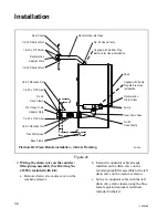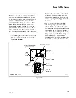
Installation
20
F232058
Mechanical Installation
(Continued)
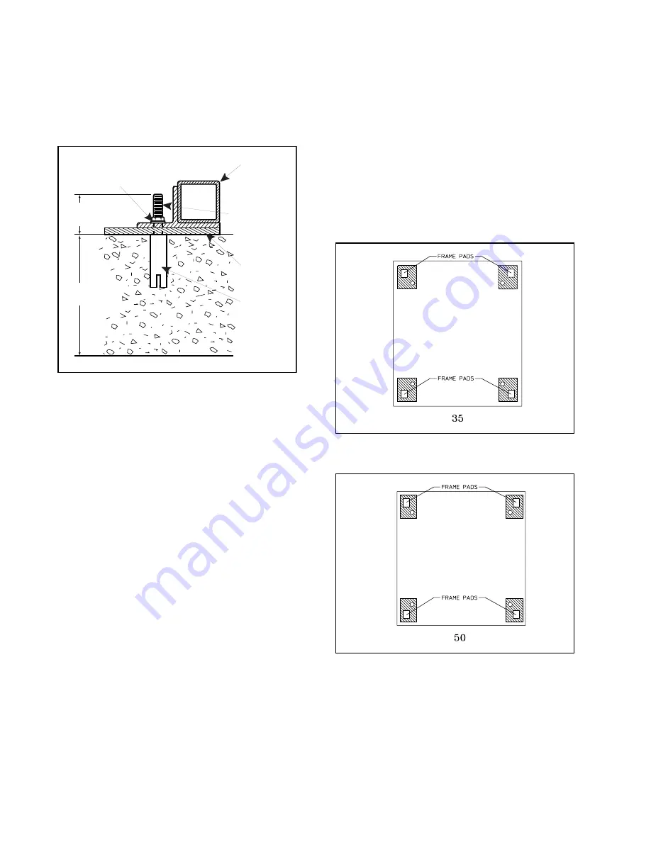
Figure 8
After the anchor bolts are installed and the
concrete has cured, proceed as follows:
1. Place the washer-extractor adjacent to the
foundation. Do not attempt to move it by
pushing on the sides. Always insert a pry
bar or other device under the bottom of the
frame of the washer-extractor to move it.
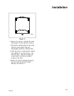
2. Remove the wood skid by unscrewing the
carriage bolts holding it to the bottom
frame of the washer-extractor.
3. Place the washer-extractor carefully over
the anchor bolts. Never attempt to lift the
machine by the door handle or by pushing
on the cover panels.
4. Raise and level the washer-extractor 1/2
inch off the floor on three points, using
spacers such as nut fasteners.
5. Fill the spaces between the washer-
extractor base and floor with a good
quality non-shrinking machinery grout to
ensure a stable installation. See Figure 9
for grouting the 35-pound capacity model.
See Figure 10 for grouting the 50-pound
capacity model. See Figure 11 for grouting
the 85-pound capacity model.
Figure 9
Figure 10
2"
(51 mm)
6"
(152 mm)
MIN
Locknut
Base Frame
Grout
Anchor
Bolt
3 1/2 x 2 Inch
Dia. Bolt
U095IEP
U096I
U097I
Summary of Contents for UF35PV
Page 2: ......
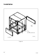
Page 24: ...Installation 22 F232058 Figure 12 B147IE3A Rear Panel Four 4 Transport Brackets Front Panel...
Page 56: ...54 NOTES F232058 Maintenance...
Page 60: ......
Page 70: ...68 NOTAS F232058 SP Seguridad...
Page 117: ...115 Mantenimiento F232058 SP...


