37
Installation
F232058
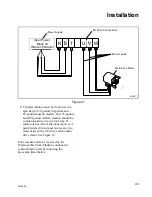
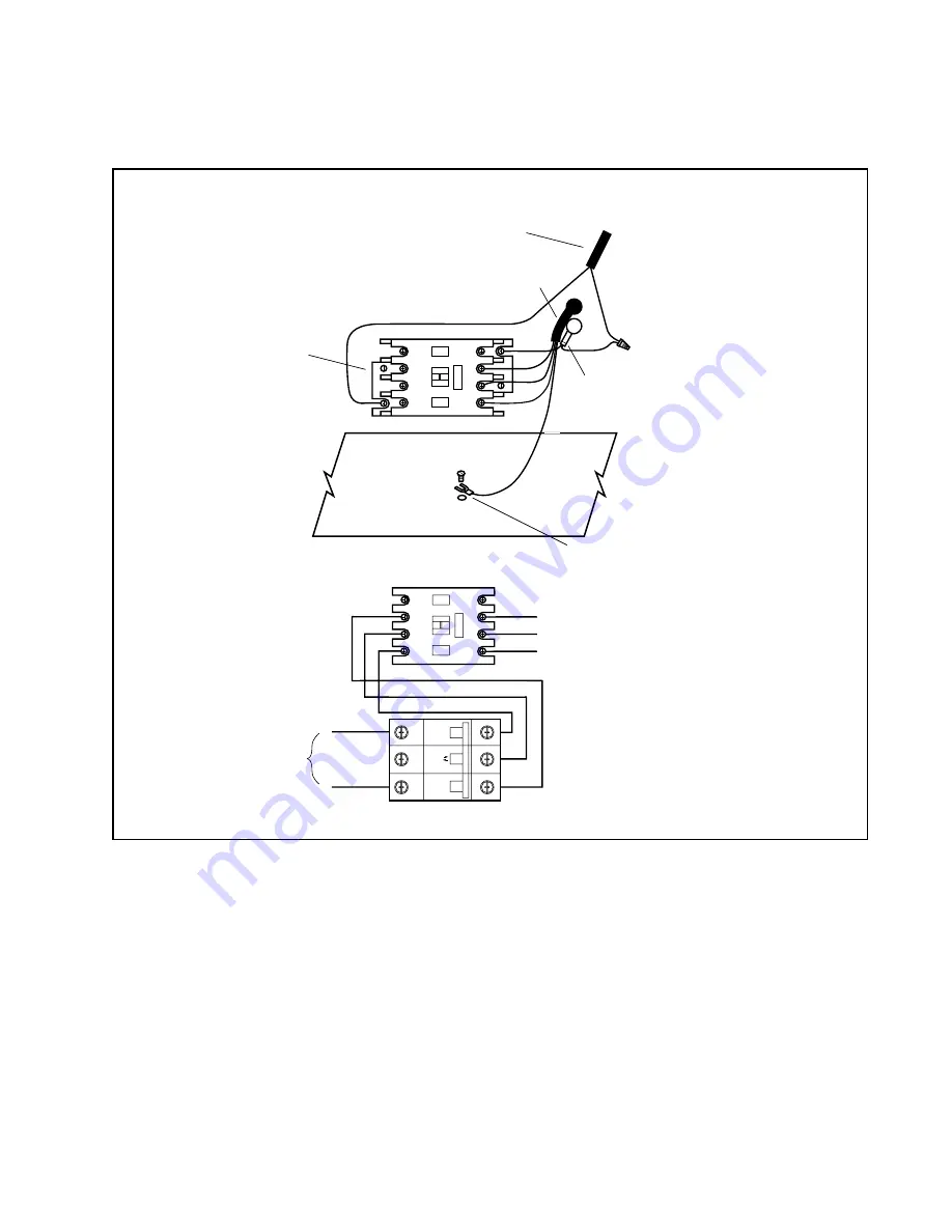
Figure 23
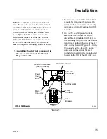
OFF
ON
T1
T2
T3
L1
L2
L3
A2
A1
NX101
L4
T4
NX101
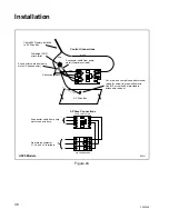
Cable #223 AC Drive Module
Splice cap
PG 13.5 connector
4-conductor cable
from pump motor
1
2
3
BLACK
RED
CIRCUIT BREAKER
BLACK
RED
2-conductor cable
from pump motor
GREEN-YELLO
W
Cut, strip, and crimp blue spade terminal
to green-yellow wire. Use No. 10 screw and nut
provided to attach wire to AC drive module.
Pump Contactor
Control Connections
3-Phase Connections
Bottom of
AC Drive Module
PUMP CONTACTOR
4-conductor cable
from pump motor
connects here.
~
From mains contactor
L1, L2, and L3 terminals
R022I
UF35 & 50 Models
Summary of Contents for UF35PV
Page 2: ......
Page 24: ...Installation 22 F232058 Figure 12 B147IE3A Rear Panel Four 4 Transport Brackets Front Panel...
Page 56: ...54 NOTES F232058 Maintenance...
Page 60: ......
Page 70: ...68 NOTAS F232058 SP Seguridad...
Page 117: ...115 Mantenimiento F232058 SP...


