background image

Installation

www.comlaundry.com

Para bajar una copia de estas instrucciones 
en espa

ñ

ol, visite www.comlaundry.com.

Washer-Extractors

UW Pocket Hardmount

2 Speed

P031I

P029I

Part No. F232085R6

January 2007

Keep These Instructions for Future Reference.

(If this machine changes ownership, this manual must accompany machine.)

Summary of Contents for UW POCKET HARDMOUNT UW35B2

Page 1: ...stas instrucciones en español visite www comlaundry com Washer Extractors UW Pocket Hardmount 2 Speed P031I P029I Part No F232085R6 January 2007 Keep These Instructions for Future Reference If this machine changes ownership this manual must accompany machine ...

Page 2: ......

Page 3: ...ns 5 Safety Decals 8 Operator Safety 9 Safe Operating Environment 9 Environmental Conditions 9 Machine Location 10 Input and Output Services 10 Misuse 10 Installation 11 Machine Overview 11 Delivery Inspection 12 Customer Service 12 Serial Plate Location 12 Machine Dimensions 16 Dimensional Clearances 16 Machine Foundation 18 Mechanical Installation 19 Mounting Bolt Installation 19 Mounting Bolt H...

Page 4: ... Copyright Alliance Laundry Systems LLC DO NOT COPY or TRANSMIT 2 F232085 Notes ...

Page 5: ... Copyright Alliance Laundry Systems LLC DO NOT COPY or TRANSMIT 3 F232085 Introduction Model Identification UW35B2 UW35P2 UW60B2 UW60P2 UW35M2 UW35S2 UW60M2 UW60S2 ...

Page 6: ... Copyright Alliance Laundry Systems LLC DO NOT COPY or TRANSMIT F232085 4 Notes ...

Page 7: ...bstances to the wash water These substances give off vapors that could ignite or explode 5 Under certain conditions hydrogen gas may be produced in a hot water system that has not been used for two weeks or more HYDROGEN GAS IS EXPLOSIVE If the hot water system has not been used for such a period before using a washing machine or combination washer dryer turn on all hot water faucets and let the w...

Page 8: ...teners or products to eliminate static unless recommended by the manufacturer of the fabric softener or product 19 Keep washer in good condition Bumping or dropping the washer can damage safety features If this occurs have washer checked by a qualified service person 20 Replace worn power cords and or loose plugs 21 Be sure water connections have a shut off valve and that fill hose connections are...

Page 9: ...lay on or around this machine Do not leave children unattended while the machine door is open SW001 DANGER This machine must be installed adjusted and serviced by qualified electrical maintenance personnel familiar with the construction and operation of this type of machinery They must also be familiar with the potential hazards involved Failure to observe this warning may result in personal injur...

Page 10: ...lure to maintain legible safety decals could result in injury to the operator or service technician To provide personal safety and keep the machine in proper working order follow all maintenance and safety procedures presented in this manual If questions regarding safety arise contact the factory immediately Use factory authorized spare parts to avoid safety hazards ...

Page 11: ... in some cases malfunction or premature damage to solid state devices that are used in some models Special cooling devices may be necessary Water pressure switches are affected by increases and decreases in temperature Every 25 F 10 C change in temperature will have a 1 effect on the water level Humidity Relative humidity above 90 may cause the machine s electronics or motors to malfunction or may...

Page 12: ... they should be covered to support light foot traffic Power For personal safety and for proper operation the machine must be grounded in accordance with state and local codes The ground connection must be to a proven earth ground not to conduit or water pipes Do not use fuses in place of the circuit breaker An easy access cutoff switch should also be provided Always disconnect power and water supp...

Page 13: ...inside the door glass produces a fan action water spray which disperses rinse water throughout the load Water enters the machine through electromechanical water valves Vacuum breakers are installed in the water inlet plumbing to prevent backflow of water A motorized drain valve holds water in the machine during the wash soak and rinse steps The drain valve is normally open which means that it clos...

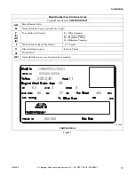
Page 14: ...otective cover advise the carrier and file a written claim immediately Customer Service If literature or replacement parts are required contact the source from which the machine was purchased or contact Alliance Laundry Systems LLC at 920 748 3950 for the name of the nearest authorized parts distributor For technical assistance call 920 748 3121 Ripon Wisconsin Serial Plate Location A record of ea...

Page 15: ...xtractor Capacity pounds dry weight P S M B Type of Electrical Control P WE 6 Computer S 12 Cycle Computer M Mechanical Timer B Millenium Computer 2 Washer Extractor Speed Capabilities 2 2 Speeds O Electrical Characteristics Refer to Table 8 U7 Design Series 0001 Option Identification varies from machine to machine PHM549N SAMPLE DECAL UW60P2OU70001 00000000000 220 240 11 30 60 60 500000 3 3 27 46...

Page 16: ...ping weight lb kg 910 413 1300 590 Export shipping volume ft3 m3 78 2 2 96 2 7 Export shipping dimensions W x D x H in mm 41 x 50 x 65 1 2 1050 x 1280 x 1670 43 x 52 1 8 x 74 1 2 1092 x 1324 x 1892 Wash Cylinder Information Cylinder diameter in mm 26 1 4 667 32 813 Cylinder depth in mm 18 3 8 467 20 508 Cylinder volume ft3 l 5 76 163 9 31 264 Perforation size in mm 3 16 4 8 3 16 4 8 Perforation op...

Page 17: ...A STD Safety switch gap setting in mm N A 0 008 0 010 0 20 0 25 Direct Steam Heating Optional Steam inlet connection size in mm 1 2 13 1 2 13 Number of steam inlets 1 1 Steam required to raise bath temperature 10 F lb 10 C kg LOW 2 1 1 5 3 3 2 4 MED 2 3 1 7 3 7 2 6 HIGH 2 7 1 9 4 1 2 9 Average consumption per cycle BHP kg hr 1 4 21 4 2 1 33 4 Electrical Heating Optional Total electrical heating ca...

Page 18: ... only They are approximate and subject to normal manufacturing tolerances If exact dimensions are required for construction purposes contact the distributor or manufacturer We reserve the right to make changes at any time without notice Table 2 UW 2 Speed Pocket Hardmount Machine Dimensions refer to Figure 2 Dimensions 35 60 in mm in mm A 30 1 8 765 35 5 8 905 B 32 1 2 826 36 5 8 930 C 23 3 4 603 ...

Page 19: ...tion 17 F232085 Figure 2 PHM388N 1 Supply Valve Box 5 Water Inlet Valves 2 Supply Dispenser 6 Power Input Area Inside 3 Door Handle 7 Drain 4 Spray Rinse Nozzle 8 Steam Connection Optional PHM388N 1 2 3 4 6 5 8 7 F A Base B Overall C E G Base D Overall H I UWP2 MODEL SHOWN ...

Page 20: ...nloading laundry may be used Care must be exercised in the design of such a base due to the force exerted by the machine during extract This base must be adequately tied in to the existing floor with rebar Static and dynamic loads on the floor or foundation are shown in Table 3 This table can be used as a reference when designing floors and foundations Table 3 Ensure that the machine is installed ...

Page 21: ...11 x 6 inch bolts the UW60 uses 3 4 10 x 8 inch bolts The bolts should be embedded in a 3500 psi minimum reinforced concrete floor that is a minimum of 6 inches 15 cm thick For mounting bolt layouts for both machines refer to Figures 3 and 4 The front of the washer extractor is the bottom of the diagram NOTE Make sure that all provided mounting bolts are used to mount the machine to the floor ...

Page 22: ...on F232085 20 Mounting Bolt Hole Locations PHM635N Figure 3 30 1 2 in 774 mm 29 in 737 mm 22 3 4 in 578 mm 28 5 8 in 727 mm 39 1 32 in 991 mm 35 1 8 in 892 mm 30 1 8 in 765 mm 26 1 8 in 664 mm 2 in 51 mm 2 in 51 mm UW35 FRONT OUTLINE OF FRAM BASE FRONT OF MACHINE 3 4 in 19 mm ...

Page 23: ... 4 PHM666N UW60 34 1 8 in 867 mm 3 4 in 19 mm 36 in 914 mm 1 1 4 in 32 mm 3 4 in 19 mm 46 13 16 in 1189 mm 44 13 16 in 1138 mm 39 1 4 in 997 mm 2 in 51 mm 2 in 51 mm 3 4 in 19 mm 1 1 4 in 32 mm 21 7 16 in 554 mm 3 4 in 19 mm 31 3 4 in 803 mm 35 5 8 in 905 mm 4 3 16 in 122 mm 9 in 229 mm FRONT OF MACHINE ...

Page 24: ...oundation cut a hole approximately 5 feet square through the existing floor Excavate to a depth of 6 inches 15 cm from the top of the existing floor Produce a pyramid shaped hole by excavating the bottom of the hole to a width 6 inches 15 cm wider on each side than the width of the top of the hole Fill with 6 inches of reinforced concrete Embed the mounting bolts or base frame as the concrete is p...

Page 25: ...cess to all frame members Refer to Figures 7 and 8 Force grout under machine base until all voids are filled Figure 7 6 Remove the spacers carefully allowing the machine to settle into the wet grout 7 Before grout sets completely make a drain opening in the rear of the washer extractor grouting with a stiff piece of wire This opening should be approximately 1 2 inch 13 mm wide to allow any surface...

Page 26: ...must be installed in accordance with all local codes and ordinances IMPORTANT The top of the vent must be 1 foot 30 cm lower than the bottom of the dispenser If proper drain size is not available or practical a surge tank is required A surge tank in conjunction with a sump pump should be used when gravity drainage is not possible such as in below ground level installations Before any deviation fro...

Page 27: ... Back of Machine 2 Drain Pipe 3 Air Gap per Local Code 4 Steel Grate 5 Drain Trough 6 Strainer 7 Waste Line 1 2 3 4 5 6 7 UW 2 Speed Pocket Hardmount Drain Information 35 60 Drain connection size I D in mm 2 3 8 60 3 76 Number of drain outlets 1 1 Drain flow capacity gal min l min 35 132 64 242 Recommended drain pit size ft3 l 5 142 6 170 UW 2 Speed Pocket Hardmount Drain Line Sizing Minimum Drain...

Page 28: ...ilter installed to keep rust and other foreign particles out of the water inlet valves Pressure of 30 85 psi 2 5 7 bar provides best performance Although the washer extractor will function properly at lower pressures increased fill times will occur Refer to Table 6 Table 7 Suitable air cushions should be installed in supply lines to prevent hammering Refer to UW 2 Speed Pocket Hardmount Water Supp...

Page 29: ...feet 15 24 to 30 48 m Use 2 sizes larger for runs greater than 100 feet 30 48 m For personal safety and for proper operation the washer extractor must be grounded in accordance with state and local codes If such codes are not available grounding must conform with the National Electric Code or other applicable codes The ground connection must be made to a proven earth ground not to conduit or water...

Page 30: ...power input block If three phase service is not available and a phase adder is used the artificial leg must be connected to L3 Refer to Figure 12 Figure 12 Refer to Figure 13 for the terminal strip for Design 5 Figure 13 P039I 1 Power Input Block 2 Ground Lug Connect to proven earth ground P039I 2 1 N White S L2 Blue R L1 Black DESIGNS 1 4 T L3 Red P037I 1 Ground Lug Connect to proven earth ground...

Page 31: ...550 575 60 3 3 5 15 14 3x2 5 Not available in this voltage O 208 240 60 3 3 7 20 12 3x4 38 50 6 3x16 S 380 50 3 3 5 15 14 3x2 5 20 25 10 3x6 W 380 415 50 3 3 5 15 14 3x2 5 22 30 10 3x6 Y 208 240 60 1 2 12 25 10 2x6 Not available in this voltage 60 D 220 240 50 3 3 11 30 10 3x6 66 80 3 3x30 F 440 480 60 3 3 7 25 10 3x6 33 40 8 3x10 G 440 50 3 3 7 25 10 3x6 30 40 8 3x10 H 380 60 3 3 7 25 10 3x6 26 3...

Page 32: ...ents are shown in Table 9 NOTE Failure to install the supplied steam filter may void the warranty Never touch internal or external steam pipes connections or components These surfaces can be extremely hot and will cause severe burns The steam must be turned off and the pipe connections and components allowed to cool before the pipe can be touched SW014 WARNING UW 2 Speed Pocket Hardmount Steam Sup...

Page 33: ...se instructions are not followed Failure to follow these instructions could damage the machine and void the warranty Figure 14 shows a typical chemical injection supply system Figure 14 Wear eye and hand protection when handling chemicals always avoid direct contact with raw chemicals Read the manufacturer s directions for accidental contact before handling chemicals Ensure an eye rinse facility a...

Page 34: ... or TRANSMIT Installation F232085 32 Figure 15 Figure 16 PHM559N 1 Tubing from Pump 2 Seal Nut 3 Tubing Ring 4 Base 5 Lid 6 Nut PHM5 2 1 4 5 6 3 DESIGN 7 P041I 1 Tubing from Pump 2 Seal Nut 3 Tubing Ring 4 Base 5 Lid 6 Nut P041I 2 1 4 5 6 3 DESIGNS 1 4 ...

Page 35: ... with the exception of the softener tube which should be routed to the outside of the cup 4 Tighten the seal nut to prevent tubing from escaping the assembly The UW 2 speed washer extractor has a polypropylene supply dispenser with five supply compartments Refer to Figure 17 Do not attempt to make chemical injection electrical connections to points other than those provided specifically for that p...

Page 36: ...stems LLC DO NOT COPY or TRANSMIT Installation F232085 34 Figure 17 PHM553N 1 Strain Relief for Liquid Chemical Supply Lines 4 Dry Supply Insert 2 Supply Dispenser Lid 5 Supply Dispenser 3 Dry Supply Cups PHM553N 1 2 3 4 5 DESIGN 7 ...

Page 37: ... DO NOT COPY or TRANSMIT Installation 35 F232085 P040I 1 Strain Relief for Liquid Chemical Supply Lines 4 Dry Supply Insert 2 Supply Dispenser Lid 5 Four Way Water Valve 3 Dry Supply Cups 6 Supply Dispenser Figure 18 1 2 3 4 6 5 DESIGNS 1 4 ...

Page 38: ...ng as this may cause damage to the washer extractor s circuitry Any injection system pump which requires 110 VAC must be powered by a separate external power source Consult the chemical injection supply system instructions for operational details Figure 19 Control Function Test The washer extractor should be cleaned after the installation is complete A function test should then be executed on the ...

Page 39: ...or washer extractors equipped with the S series microcomputer select an appropriate cycle from the 12 cycles listed in the S series Operation Programming manual F232087 Run the complete cycle checking operation of all functions As an alternative a test cycle is available for the S series microcomputer To access the test cycle verify that the RUN PROGRAM mode toggle switch is in the RUN position Pr...

Page 40: ......

Reviews: