background image

Installation/Operation/Maintenance

Washer-Extractors

Cabinet Freestanding

Refer to Page 9 for Model Identification

Original Instructions
Keep These Instructions for Future Reference.
CAUTION: Read the instructions before using the machine.

(If this machine changes ownership, this manual must accompany machine.)

www.alliancelaundry.com

Part No. D1598ENR10

February 2021

Summary of Contents for UY105 PRO

Page 1: ...to Page 9 for Model Identification Original Instructions Keep These Instructions for Future Reference CAUTION Read the instructions before using the machine If this machine changes ownership this manual must accompany machine www alliancelaundry com Part No D1598ENR10 February 2021 ...

Page 2: ......

Page 3: ...tallation If Required Models with Base Frame with Built In Filter 26 Shipping Brace Removal 28 Machine Installation 29 Elevated Base Frame Installation with Existing Floor Base Frame Supplied by Manufacturer 29 Machine Anchoring Models with Base Frame with Built in Filter 29 Weighing System Installation 18 kg 28 kg 40 lb 70 lb 180 L 280 L Models 31 Drain Connection 33 Drain Valve 34 Drain Pump 6 5...

Page 4: ...pecifications 51 Electrical Specifications North American Models 57 Steam Requirements Steam Heat Option Only 59 Steam Valve Installation 59 Supply Dispensing 60 Connection of External Liquid Supplies 60 Electrical Connection of External Liquid Soap Supply System 61 External Wait Control 62 Chemical Injection Supply System 63 Operation 64 Operating Instructions 64 Power Cut 65 Automatic Door lock ...

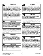
Page 5: ...tiles containing traces of the following substances to the wash water gasoline kerosene waxes cooking oils vegetable oils machine oils dry clean ing solvents flammable chemicals thinners or other flamma ble or explosive substances These substances give off vapors that could ignite explode or cause the fabric to catch fire by itself Under certain conditions hydrogen gas may be produced in a hot wat...

Page 6: ...ains charged with high voltage for some time after power ing OFF This is an imminently hazardous situation that if not avoided will cause severe personal injury or death Before starting inspection of the inverter check for residual voltage across main circuit terminals and This voltage must be below 30 VDC before the servicer can access the inverter for inspection Do not repair or replace any part...

Page 7: ...or prop erty damage W703 WARNING Never interfere with the setting of the door handle Never try to modify the setting or repair the handle Any interference with its setting may lead to serious risk for the operator A damaged or incorrectly func tioning door handle must always be immediately re placed with a new original part C014 CAUTION To avoid premature bearing failure do not operate the machine...

Page 8: ...use in blocks of flats or in launderettes any other similar applications Installation of these machines must fully conform to the instruc tions contained in this manual The following maintenance checks must be performed daily 1 Verify that all warning labels are present and legible replace as necessary 2 Check door interlock before starting operation of the ma chine a Attempt to start the machine ...

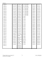
Page 9: ...F HYX065F HYX080F HYX105F HYX135F HYX180F HYX240F HYX280F SY105_QED SY105_QED SELECT SY135_QED SY135_QED SELECT SY180_QED SY180_QED SELECT SY20_QED SELECT SY240_QED SY240_QED SELECT SY25_QED SELECT SY280_QED SY280_QED SELECT SY30_QED SELECT SY40_QED SELECT SY55_QED SELECT SY65_QED SY65_QED SELECT SY70_QED SELECT SY80_QED SY80_QED SELECT SYB180A SYB180D SYC065A SYC065D SYC080A SYC080D SYC105A SYC10...

Page 10: ...UY20_PRO FORM SYR105D SYR135D SYR180D SYR240D UY240_PROFORM UY25_PROFORM UY280_PROFORM UY30_PROFORM UY40_PROFORM UY55_PROFORM UY65_PROFORM UY70_PROFORM UY80_PROFORM UYB180I UYC065I UYC080I UYC105I UYC135I UYC180I UYC240I UYC280I UYE065I UYE080I UYE105I UYE135I UYE180I UYE240I UYE280I UYG065I UYG080I UYG105I SYR280D UYR065I UYR080I UYR105I UYG135I UYG180I UYG240I UYG280I UYH065I UYH080I UYH105I UYH...

Page 11: ...ound on the serial number The last two characters indicate first the year and then the month Refer to Table 1 and Table 2 For example a unit with serial number 520I000001DK was manufactured in May 2015 Manufacturing Date Year Year Serial Number Character 2009 P 2010 R 2011 T 2012 V 2013 X 2014 B 2015 D 2016 F 2017 H 2018 K 2019 M Table 1 continues Manufacturing Date Year Year Serial Number Charact...

Page 12: ...shipping receipt is signed or advise the carrier of the condition as soon as it is discovered Replacement Parts If literature or replacement parts are required contact the source from which the machine was purchased or contact Alliance Laun dry Systems at 1 920 748 3950 for the name and address of the nearest authorized parts distributor Customer Service For technical assistance contact your local...

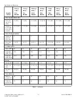
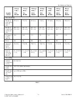
Page 13: ...95 38 18 970 38 18 970 38 18 970 Overall depth in mm 29 13 740 31 10 790 31 29 795 37 20 945 38 18 970 43 50 1105 46 65 1185 Weight and Shipping Information Net weight lbs kg 375 170 408 185 463 210 563 255 838 380 948 430 1092 495 Shipping weight lbs kg 397 180 441 200 518 235 606 275 871 395 992 450 1135 515 Wash Cylinder Information Cylinder di ameter in mm 20 87 530 20 87 530 24 40 620 24 40 6...

Page 14: ... 1 1 1 1 1 Motor Size hp kW 1 0 75 1 0 75 1 48 1 1 2 01 1 5 2 95 2 20 4 02 3 0 4 02 3 0 Cylinder Speeds Wash RPM 49 49 49 49 42 42 42 Extraction RPM 350G N A N A N A N A N A N A 915 Extraction RPM 400G 1165 1165 1075 1075 980 980 N A Heating Electric kW 6 9 4 6 6 9 4 6 6 9 12 9 12 12 18 18 21 9 Steam psi bar 15 116 1 8 15 116 1 8 15 116 1 8 15 116 1 8 15 116 1 8 15 116 1 8 15 116 1 8 Hot water F C...

Page 15: ... 1 1 Frequency of dynamic load Hz 19 4 19 4 17 9 17 9 16 3 16 3 15 25 G factor 400 400 400 400 400 400 350 Static floor pressure lbs ft2 kN m2 96 4 61 98 4 68 99 4 73 100 4 78 121 5 8 113 5 43 116 5 53 Dynamic floor pres sure lbs ft2 kN m2 83 23 3 95 1 1 81 21 3 87 1 02 84 19 4 0 0 91 84 16 4 04 0 75 99 17 4 73 0 83 98 24 4 71 1 13 99 22 4 76 1 05 General Data Ambient Temperature F C 41 95 5 35 Re...

Page 16: ...oap connection 7 Recyled water inlet 8 Steam valve connection 9 Recycled water valve cable inlet 10 Cold water inlet soft 11 Cold water inlet hard 12 Electrical connection 13 Hot water inlet 14 Main switch 15 Heating change over switch 16 Liquid soap pump eletrical connection 17 Fuses 18 USB port 19 PC programming connection 20 Drain Valve 1 2 applicable for wash bath sample on request only 28 kg ...

Page 17: ...6 39 80 1011 42 76 1086 K 40 35 1025 40 35 1025 44 68 1135 44 68 1135 51 96 1320 51 96 1320 51 96 1320 L 39 76 1010 39 76 1010 44 09 1120 44 09 1120 51 08 1297 5 51 08 1297 5 51 37 1305 M 36 22 920 36 22 920 40 55 1030 40 55 1030 47 83 1215 47 83 1215 47 83 1215 N 18 89 480 18 89 480 19 92 506 19 92 506 19 29 490 19 29 490 19 29 490 O 3 46 88 3 46 88 3 46 88 3 46 88 4 27 108 5 4 27 108 5 4 27 108 ...

Page 18: ...els in mm Y 4 44 113 4 44 113 4 44 113 4 44 113 4 44 113 4 44 113 4 44 113 Table 4 Machine Dimensions Machines with Optional Filter Tanks for Mops 65 L Models 75 L Models 105 L Models 135 L Models 180 L Models 240 L Models 280 L Models A B C D E F G H I J K L M N O P Q R S T U V W X Y Z AA BB CFS696N_SVG Figure 3 Specifications and Dimensions Copyright Alliance Laundry Systems LLC DO NOT COPY or T...

Page 19: ... K 31 30 795 L 8 43 214 M 51 54 1309 N 18 39 467 O 31 30 795 P 8 43 214 Q 53 43 1357 R 19 09 485 S 38 19 970 T 8 98 228 U 58 74 1492 V 19 09 485 W 38 19 970 X 8 98 228 Y 61 69 1567 Z 19 09 485 AA 38 19 970 BB 8 98 228 Table 5 Specifications and Dimensions Copyright Alliance Laundry Systems LLC DO NOT COPY or TRANSMIT 19 Part No D1598ENR10 ...

Page 20: ...3 1408 55 43 1408 59 76 1518 59 76 1518 65 12 1654 65 12 1654 65 12 1654 E 57 64 1464 57 64 1464 61 97 1574 61 97 1574 67 32 1710 67 32 1710 67 32 1710 F 8 35 212 8 35 212 8 35 212 8 35 212 6 38 162 6 38 162 6 38 162 G 14 69 373 14 69 373 14 69 373 14 69 373 12 72 323 12 72 323 12 72 323 H 25 28 642 27 24 692 27 24 692 33 07 840 34 21 869 39 53 1004 42 48 1079 J 10 16 258 8 23 209 11 38 289 7 09 1...

Page 21: ...6 2 99 76 N 9 84 250 9 84 250 9 84 250 9 84 250 7 87 200 7 87 200 7 87 200 O 17 24 438 17 24 438 17 24 438 17 24 438 16 06 408 16 06 408 16 06 408 P 13 78 350 13 78 350 13 78 350 13 78 350 11 81 300 11 81 300 11 81 300 Mounting Bolt Hole Locations A C B D E H F G I J K CZW36N Figure 5 Specifications and Dimensions Copyright Alliance Laundry Systems LLC DO NOT COPY or TRANSMIT 21 Part No D1598ENR10...

Page 22: ... I 27 95 710 27 95 710 31 29 795 31 29 795 J 25 25 641 5 27 22 691 5 27 22 691 5 33 12 841 5 K 21 65 550 23 62 600 24 02 610 26 77 680 Table 6 Mounting Bolt Hole Locations in mm Specification 18 kg 40 lb 180 L Models 24 kg 55 lb 240 L Models 28 kg 70 lb 280 L Models A 30 90 785 30 90 785 30 90 785 B 22 04 560 27 36 695 30 31 770 C 3 64 92 5 3 64 92 5 3 64 92 5 D 8 32 211 5 8 32 211 5 8 32 211 5 E ...

Page 23: ...280 L Models J 34 31 871 5 39 62 1006 5 42 60 1082 K 25 98 660 31 30 795 34 25 870 Table 7 Mounting Bolt Hole Locations Models with Optional Filter Tanks for Mops CZW153N_SVG A B C E D F G Figure 6 Specifications and Dimensions Copyright Alliance Laundry Systems LLC DO NOT COPY or TRANSMIT 23 Part No D1598ENR10 ...

Page 24: ... 33 46 850 B 21 26 540 23 23 590 23 23 590 27 95 710 26 30 668 31 61 803 34 57 878 C 1 77 45 1 77 45 1 77 45 1 77 45 1 77 45 1 77 45 1 77 45 D 2 24 57 2 24 57 2 24 57 3 35 85 6 10 155 6 10 155 6 10 155 E 2 32 59 2 32 59 2 24 57 2 24 57 2 36 60 2 36 60 2 36 60 F 63 16 63 16 63 16 63 16 63 16 63 16 63 16 G 25 28 642 27 24 692 27 24 692 33 07 840 34 21 869 39 53 1004 42 48 1079 Table 8 Specifications...

Page 25: ... A Distance of ma chine to side wall or other machine minimum 0 79 20 0 79 20 0 79 20 0 79 20 0 79 20 0 79 20 0 79 20 B Distance to wall minimum 20 500 20 500 20 500 20 500 20 500 20 500 20 500 C Dimensional clear ance above ma chine minimum 35 43 900 35 43 900 35 43 900 35 43 900 43 31 1100 43 31 1100 43 31 1100 Table 9 Specifications and Dimensions Copyright Alliance Laundry Systems LLC DO NOT C...

Page 26: ...itch refer to Every 6 Months Mounting Bolt Installation If Required Models with Base Frame with Built In Filter NOTE Machines do not need to be mounted by means of anchoring bolts If anchoring is necessary perform the following steps Refer to Figure 8 1 Drill two holes for the anchoring bolts Hole diameter in ma chine base is 0 47 in 12 mm 2 Place the machine adjacent to mounting foundation Do not...

Page 27: ...h the machine 3 Spring washer Supplied with the machine 4 Washer Supplied with the machine 5 Base frame 6 Anchor bolt Supplied with the machine 7 Concrete floor Figure 8 Installation Copyright Alliance Laundry Systems LLC DO NOT COPY or TRANSMIT 27 Part No D1598ENR10 ...

Page 28: ...older 3 Front panel 4 Rear panel Figure 9 2 Remove both front metal transport holders 3 Remove both rear transport holders IMPORTANT The machine may not be moved with the shipping braces removed Save the shipping braces for future use Installation Copyright Alliance Laundry Systems LLC DO NOT COPY or TRANSMIT 28 Part No D1598ENR10 ...

Page 29: ...nd the BACK label is at the back of the machine 4 Make sure the base frame is level 5 Place the washers 4 and nuts 5 on the anchoring bolts and tighen to a torque of 80 Nm Refer to Figure 10 6 Remove the transport packaging from the machine 7 Remove the front and rear panels from the machine 8 Remove the bolts fastening the machine to the pallet but DO NOT mount the adjustable feet from the machin...

Page 30: ...by an incorrect installation CAUTION The nuts of the anchoring bolts must be tightened using a torque limiting wrench Refer to Table 10 Do not tighten the nuts of the anchoring bolts until the concrete base around the bolts is completely cured W1064 CZW149N_SVG L 1 2 3 4 6 5 1 Plinth 2 Anchor bolt 3 Anchor washer 4 Washer 5 Anchor Body 6 Floor Figure 11 Installation Copyright Alliance Laundry Syst...

Page 31: ...4 70 60 44 3 94 100 0 71 18 Table 10 1 Check the position of the machine base frame with a water level 2 Drill a hole for the anchoring bolt based on the required ma chine placement Refer to Figure 11 3 Remove washer and bolt from the anchoring bolt and install anchoring bolt into the pre drilled hole 4 Install the plinth base 5 Install washer and nut Tighten nut Weighing System Installation 18 kg...

Page 32: ...herefore anything that you place on to the machine or anything that is in physical contact with it influences the weighing process Make sure that the water connection as regards the pressure in the hoses does not interfere with the weighing The ho ses must no pull or push the machine in any direc tion or prop it up in any way 11 Install the covers Refer to Figure 12 12 Check and if necessary adjus...

Page 33: ...Drain Connection 1 Drain connection Figure 15 Installation Copyright Alliance Laundry Systems LLC DO NOT COPY or TRANSMIT 33 Part No D1598ENR10 ...

Page 34: ...ock or siphon ing Connect a 3 inch 76 mm pipe or rubber hose to the machine s drain pipe ensuring a downward flow from the machine Avoid sharp bends which may prevent proper draining The drainage pipe should be located over a floor drain drainage channel Installation Copyright Alliance Laundry Systems LLC DO NOT COPY or TRANSMIT 34 Part No D1598ENR10 ...

Page 35: ... 75 3 75 B 4 17 106 4 4 112 4 4 112 4 4 112 5 21 132 5 5 21 132 5 5 21 132 5 C minimum 0 79 20 0 79 20 0 79 20 0 79 20 0 79 20 0 79 20 0 79 20 D minimum 3 94 100 3 94 100 3 94 100 3 94 100 3 94 100 3 94 100 3 94 100 Table 11 Drain Connections Specification Model Requirement Drain connection number All 1 Drain connection size in mm All 3 76 Average flow rate of draining gal min l min All 55 48 210 ...

Page 36: ...the drain pipe will work If the main drain pipe cannot be sufficiently ven ted install a vent per machine Every time a machine is coupled on the drainpipe the diameter of the tube or the width of the waste channel must increase Refer to Figure 17 The diameters of drain pipe for machines with two drain valves must have dimensions suitable for double the value of water flow CHM2481N_SVG 2 C B A 1 1 ...

Page 37: ...than the water level to provide sufficient si phon effect In order to achieve good draining the hose must not bend at a sharp angle Refer to Figure 18 1 Drain hose bend Figure 18 Venting WARNING Vapours escape from the machine through the air vent opening Do not cover C238 Installation Copyright Alliance Laundry Systems LLC DO NOT COPY or TRANSMIT 37 Part No D1598ENR10 ...

Page 38: ...e duction piece 1 Hose 2 Reduction 3 Seal 4 Valve Figure 20 NOTE Models outside of North America For 6 5 kg 14 lb 65 L 7 5 kg 20 lb 75 L 10 5 kg 25 lb 105 L 13 5 kg 30 lb 135 L 18 kg 40 lb 180 L and 24 kg 55 lb 240 L Models to connect cold water use a hose with plastic elbow To connect hot water use a hose with metal elbow Do not re use water hoses only use new water hoses The appliance has been d...

Page 39: ...ctions should be supplied by a hot and a cold water line of at least the sizes shown in Water Supply Line Sizing Installation of additional machines will require proportionately larger water lines Connections should be supplied by a hot and a cold water line per national and local codes and in accordance with IEC 61770 To connect water service to a machine with hoses use the follow ing procedure 1...

Page 40: ...watermark is provided with the unit and must be fitted at the point of connection s between the sup ply and the fitting Refer to Figure 25 CZB92N Figure 24 Connections should be supplied by a hot and a cold water line per national and local codes and in accordance with AS NZS 3500 1 1 Insert rubber washers and filter screens from accessories bag in water fill hose couplings two hoses supplied with...

Page 41: ...ose couplings 7 Continue tightening and rechecking until no leaks are found FLW2216N_SVG HOT COLD 7 6 5 4 3 2 1 1 Tap 2 Fill Hoses 3 Install this end of hose to valve connections at rear of washer 4 Plain Rubber Washer 5 Install this end of hose to water supply tab Black colored coupling for BSPP thread 6 Filter Screens 7 Dual Check Valves Figure 25 Installation Copyright Alliance Laundry Systems ...

Page 42: ...hose The water reuse system must be fitted with a filter which must be regularly and thoroughly cleaned based on water quality This cleaning prevents prolongation of filling up times and malfunc tion of water valves Reused Water Treatment The reused water must be filtered before entering the water reuse tank A mechanical filter must be installed which filters off small particles fluff buttons pape...

Page 43: ...ect electric power and wait ten 10 minutes before servicing W911 WARNING Dangerous voltages are present inside the machine Only qualified personnel should attempt adjustments and troubleshooting Disconnect power from the ma chine before removing any cover and guards and before attempting any service procedures W736 WARNING Hazardous Voltage Can cause shock burn or death Verify that a ground wire f...

Page 44: ...t Circuit Interrupter GFCI Appliance Leakage Current Interrupter ALCI or Earth Ground Leakage Current Breaker When locally allowed an RCD must be installed In some power network earthing systems an RCD may not be allowed The RCD must have the following specifications Tripping current of 100mA if not locally available allowed use a 30mA trip current preferably selective type with small time delay s...

Page 45: ...5A 13 2 5 13 2 5 25A 20A 20A 11 4 11 4 40A 40A 32A 30A 9 6 9 6 63A 50A 50A 7 10 7 10 80A 63A 5 16 5 16 100A 80A 3 25 5 16 125A 100A 2 35 3 25 Table 16 To connect the supply cable the following steps must be per formed 1 Insert cable through opening on rear panel Insure a strain re lief is used so the supply cable can not move 2 Strip the conductor ends Refer to Figure 29 The protection conductor m...

Page 46: ...erican Models 1 Main switch 2 Strain relief 3 Sag of inlet cable 4 L3 5 L2 6 L1 Figure 31 Machine Protective Earth Connection and Equipotential Bonding If there are other washers or appliances with exposed conductive parts which can touch simultaneously make sure to make equi potential bonding between all these appliances The external pro tective terminal for this purpose is located on the rear pa...

Page 47: ...is leg should be identified throughout the system with red or orange tape on the wire at each connection point The stinger leg should be connected to the center Phase B on the reactor Table 17 Input Voltage Requirements For voltages above or below listed specifications contact your power company or local electrician If machine is intended for four wire service a neutral leg must be provided by pow...

Page 48: ... larger for runs greater than 100 feet 30 m Single Phase Connections Single Phase Connection North American Models Connect the electrical service s wires to the machine s electrical connection terminal as shown Electrical Service Wire Machine s Electrical Connection Terminal L1 L1 L2 L2 PE PE Ground Table 18 Electrical Connection Terminal Block Figure 32 North American Models with Single Phase Con...

Page 49: ...erminal L1 L1 L2 L2 L3 L3 PE PE Ground Table 20 North American Models with Three Phase Connec tion Figure 36 Three Phase Connection Models Outside of North America Connect the electrical service s wires to the machine s electrical connection terminal as shown Electrical Service Wire Machine s Electrical Connection Terminal U U V V W W PE PE Ground Table 21 Electrical Connection Terminal Block V W ...

Page 50: ...ormer must be se lected For example if the voltage range is 208 240V the connec ted terminal transformer will be 240V If the supply voltage is 208V redirect the voltage wire to the 208V terminal Frequency Settings The machines are designed and manufactured for 50 60HZ Refer to the serial plate for frequency information specific to your ma chine Make sure the frequency is always within the limits s...

Page 51: ...1 N 0 85 6 6 10 3 6 17 9 3 20 5 2 24 9 4 6 32 200 240 50 60 3 3 L1 L2 L3 0 85 6 6 10 6 7 20 6 25 9 7 27 5 9 32 380 415 N 50 60 3 4 L1 L2 L3 N 0 85 6 6 10 5 3 10 4 6 16 6 7 13 5 6 16 9 7 18 9 20 380 415 50 60 3 3 L1 L2 L3 0 85 2 4 10 6 7 9 9 6 16 9 7 15 3 9 20 440 480 50 60 3 3 L1 L2 L3 0 85 2 4 10 7 7 11 6 7 16 9 7 13 8 9 16 Table 22 Installation Copyright Alliance Laundry Systems LLC DO NOT COPY ...

Page 52: ...10 3 6 18 3 20 5 2 25 1 4 6 32 200 240 50 60 3 3 L1 L2 L3 0 85 6 7 10 6 7 20 2 6 25 9 7 27 9 9 32 380 415 N 50 60 3 4 L1 L2 L3 N 0 85 6 7 10 5 3 10 4 6 16 6 7 13 7 6 16 9 7 18 2 9 20 380 415 50 60 3 3 L1 L2 L3 0 85 2 5 10 6 7 10 6 16 9 7 15 4 9 20 440 480 50 60 3 3 L1 L2 L3 0 85 2 5 10 7 7 11 7 7 16 9 7 13 9 9 16 Table 23 Installation Copyright Alliance Laundry Systems LLC DO NOT COPY or TRANSMIT ...

Page 53: ...5 4 6 32 200 240 50 60 3 3 L1 L2 L3 1 2 9 8 16 6 8 20 5 6 25 9 8 28 1 9 32 12 8 35 6 12 40 380 415 N 50 60 3 4 L1 L2 L3 N 1 2 9 8 16 6 8 14 1 6 16 9 8 18 5 9 20 12 8 22 8 12 25 380 415 50 60 3 3 L1 L2 L3 1 2 3 2 10 6 8 10 1 6 16 9 8 15 5 9 16 12 8 19 9 12 25 440 480 50 60 3 3 L1 L2 L3 1 2 3 2 10 7 8 12 8 7 16 9 8 14 9 16 12 8 18 2 12 25 Table 24 Installation Copyright Alliance Laundry Systems LLC ...

Page 54: ...L1 L2 L3 1 6 10 1 16 7 1 22 6 25 10 1 29 6 9 32 13 1 37 2 12 40 14 9 41 7 13 8 50 380 415 N 50 60 3 4 L1 L2 L3 N 1 6 10 1 16 7 1 13 6 16 10 1 18 9 20 13 1 22 6 12 25 14 9 27 13 8 32 380 415 50 60 3 3 L1 L2 L3 1 6 3 6 10 7 1 11 6 6 16 10 1 16 9 20 13 1 19 9 12 20 14 9 22 5 13 8 32 440 480 50 60 3 3 L1 L2 L3 1 6 3 6 10 8 1 13 2 7 16 10 1 14 8 9 16 13 1 18 7 12 25 Table 25 Installation Copyright Alli...

Page 55: ...3 14 2 20 N A N A N A 200 240 50 60 3 3 L1 L2 L3 2 3 14 2 20 13 5 37 9 12 40 19 5 53 3 18 63 380 415 N 50 60 3 4 L1 L2 L3 N 2 3 14 2 20 13 5 23 1 12 25 19 5 31 9 18 32 380 415 50 60 3 3 L1 L2 L3 2 3 5 2 10 13 5 20 9 12 25 19 5 30 5 18 32 440 480 50 60 3 3 L1 L2 L3 2 3 5 2 10 13 5 19 7 12 25 19 5 27 2 18 32 Table 26 Installation Copyright Alliance Laundry Systems LLC DO NOT COPY or TRANSMIT 55 Part...

Page 56: ...se A 200 240 50 60 1 2 L1 L2 or L1 N 3 1 15 20 N A N A N A 200 240 50 60 3 3 L1 L2 L3 3 1 15 20 20 54 3 18 63 380 415 N 50 60 3 4 L1 L2 L3 N 3 1 15 20 20 31 9 18 32 380 415 50 60 3 3 L1 L2 L3 3 1 7 1 10 20 31 5 18 32 440 480 50 60 3 3 L1 L2 L3 3 1 7 1 10 20 28 2 18 32 Table 27 Installation Copyright Alliance Laundry Systems LLC DO NOT COPY or TRANSMIT 56 Part No D1598ENR10 ...

Page 57: ...200 240 50 60 1 2 L1 L2 or L1 N 3 1 16 20 N A N A N A 200 240 50 60 3 3 L1 L2 L3 3 1 16 20 23 9 64 21 9 80 380 415 N 50 60 3 4 L1 L2 L3 N 3 1 16 20 23 9 40 5 21 9 50 380 415 50 60 3 3 L1 L2 L3 3 1 7 2 10 23 9 37 21 9 40 440 480 50 60 3 3 L1 L2 L3 3 1 7 2 10 23 9 34 21 9 40 Table 28 Installation Copyright Alliance Laundry Systems LLC DO NOT COPY or TRANSMIT 57 Part No D1598ENR10 ...

Page 58: ...L2 or L1 N 9 8 15 14 2 5 N 440 480 60 3 3 L1 L2 L3 3 2 10 14 2 5 Table 30 13 5 kg 30 lb 135 L Models Code Voltage V Frequen cy Hz Phase Wire Full Load Amps A Circuit Breaker CSA A AWG mm2 X 200 240 60 1 3 2 L1 L2 or L1 N 10 1 15 14 2 5 N 440 480 60 3 3 L1 L2 L3 3 6 10 14 2 5 Table 31 18 kg 40 lb 180 L Models Code Voltage V Frequen cy Hz Phase Wire Full Load Amps A Circuit Breaker CSA A AWG mm2 X 2...

Page 59: ... piping in accordance with approved commercial steam practices Steam re quirements are shown in Table 35 Specification Requirement Steam inlet connection size in BSP 1 2 Steam pressure PSI bar 15 116 1 8 Table 35 IMPORTANT It is necessary to insert a filter with per meability up to 0 0118 in 300 µm in front of the steam valve Dirt larger than 0 0118 in 300 µm may damage the steam valve and cause l...

Page 60: ...IMPORTANT Always use liquid soap pumps with a flow that bring the requested quantity in less than 30 sec IMPORTANT Start pumping immediately after water valves are open The incoming water dilutes the liquid soap and brings it into the tub assembly Secure the location of the wiring and hoses so they can not be pinched damaged or rubbed Before you start to use liquid soap check with your liquid soap...

Page 61: ...Supply System The power supply of the external liquid soap supply system has to be connected to an external electrical source Only authorized workers with valid qualifications must execute the electrical con nection on the machine according to valid local standards The correction connection can be found on the wiring diagram inclu ded with the machine Do not connect the liquid soap pump sys tem in...

Page 62: ... Such connection is possible only with machines which had been or dered with the Heating Delay Waiting for Detergent option Valve Panel Rear View 1 External Supply Hose Connections 2 Cable Bushing 3 Control Signals Terminal Box Figure 42 Installation Copyright Alliance Laundry Systems LLC DO NOT COPY or TRANSMIT 62 Part No D1598ENR10 ...

Page 63: ...tor Therefore all chemical supply dispenser pumps should be moun ted below the washerextractor s injection point All dispenser tubing should also run below the injection point Loops do not prevent drips if these instructions are not followed Failure to fol low these instructions could damage the machine and void the warranty Figure 43 shows a typical chemical injection supply system Chemical Injec...

Page 64: ...63 13 5 kg 30 lb 135 L 84 81 18 kg 40 lb 180 L 69 5 90 24 kg 55 lb 240 L 69 2 118 28 kg 70 lb 280 L 64 3 128 Table 37 NOTE Table is for orientational purposes only as is applicable for flat mops with length 40 cm and weight 0 140 g U003I_SVG Figure 44 4 Close the door by applying moderate pressure on the door handle and simultaneously turning door handle partially to the left 5 NOTE Make sure the ...

Page 65: ...t numeric keypad If a power cut occurs during the wash process and the door re mains closed and locked the wash program will after the power supply has been restored automatically continue in the program beginning from the step in which the program was interrupted For machines fitted with an automatic door lock unlocking mod ule refer to Automatic Door lock Unlocking Module section If during the p...

Page 66: ...ock and interlock are not functioning properly dis connect power and call a service technician 2 Check the machine for leaks a Start an unloaded cycle to fill the machine b Verify that door and door gasket do not leak c Verify that the drain valve is operating and that the drain system is free from obstruction If water does not leak out during the first wash segment the drain valve is closed and f...

Page 67: ...eck and clean the filter daily Failure to check and clean the filter can lead to incorrect function of the equipment which results in insufficient drainage of waste water into the sewer 1 2 3 CFS673N_SVG 1 Filter 2 Filter in working position 3 Filter in partially ejected position Figure 46 Box dismounting procedure 1 Remove the filter Refer to Figure 47 CFS674N_SVG 1 1 Filter Figure 47 2 Remove th...

Page 68: ...r does not leak out during the first wash segment the drain valve is closed and function ing properly 3 Visually check all hoses and connections inside machine for leaks 4 Make sure that control components are protected against moisture and dust during the clean up Wipe and clean the machine inside 5 For models with electric heat check the tightening of the con tacts of heating elements terminals ...

Page 69: ...eattach pump lid and front panel of cabinet 3 Remove dust or dirt and verify functionality of the following a Inverter cooling fin WARNING Before removing top or back panel of machine switch power off and wait for at least 10 mi nutes Before starting inspection of frequency inverter check for residual voltage across main circuit terminals This voltage must be below 30 VDC before you can access the...

Page 70: ...closing torque 8 8 After a cycle has been completed check the shock absorb ers to see if they are warm If the shock absorbers aren t warm just after a wash cycle has been completed replace them Care of Stainless Steel Remove dirt and grease with detergent and water Thoroughly rinse and dry after washing Avoid contact with dissimilar metals to prevent galvanic cor rosion when salty or acidic soluti...

Page 71: ... manufacturer s warranty Locate the pump and tubing below the machine s injection point to prevent siphoning of chemicals into the machine Maintenance Copyright Alliance Laundry Systems LLC DO NOT COPY or TRANSMIT 71 Part No D1598ENR10 ...

Page 72: ...nd precautions when disassembling the washer to avoid injury from glass or sharp metal edges W908 Disposal of Unit This appliance is marked according to the European directive 2002 96 EC on Waste Electrical and Electronic Equipment WEEE This symbol on the product or on its packaging indicates that this product shall not be treated as household waste Refer to Figure 55 Instead it shall be handed ov...

Page 73: ... O O This table is prepared in accordance with the provisions of SJ T 11364 O Indicates that the content of said hazardous substance in all of the homogenous materials in the component is within the limits required by GB T 26572 X Indicates that the content of said hazardous substance exceeds the limits required by GB T 26572 in at least one homogenous material in the component All parts named in ...

Reviews: