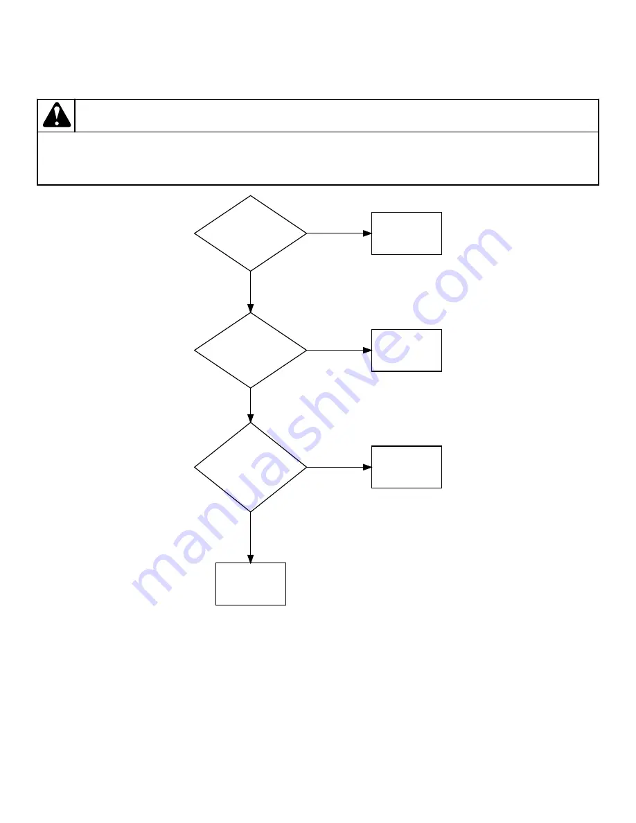
Drive Motor - Motor Windings
Internal Wiring of Dryer Motor Switch
for wiring schematic.
WARNING
Disconnect electric power to dryer before performing any of the following steps or when replacing inoperative
motor switch.
W290
Start Winding: 1 – 2
Ohms between terminal
3 wire and orange or
copper wire on the
back of switch.
Run Main Winding: 1 –
2 Ohms between
terminal 5 wire and
orange or copper wire
on the back of switch
wire.
Yes
Inoperative start
winding. Replace
motor.
No
Protector: Continuity
exists between orange
or copper wire on
back of switch and
brown/blue wire in
terminal 4.
Yes
Inoperative run main
winding. Replace
motor.
No
All motor windings
check O.K.
Yes
Inoperative
protector. Replace
motor.
No
Motor Switch
1. Remove motor and exhaust fan assembly.
2. Remove the two motor switch attaching screws. Refer to
. Disconnect switch leads. Remove motor switch.
3. Remove thermal overload protector.
NOTE: The thermal overload protector is unique to
the motor from which it was removed and should
only be used on that motor. To reduce the risk of
overheating the motor, do not use any thermal over-
load protector other than the one taken from the in-
operative motor switch in step 3.
a.
Motor with Switch on Blower End
. Using a small bladed
screwdriver, press the thermal overload protector mount-
ing tab downward and remove the thermal overload pro-
tector from the inoperative motor switch. Refer to
.
Test Procedures
©
Copyright, Alliance Laundry Systems LLC -
DO NOT COPY or TRANSMIT
57
Part No. D515519R3
Summary of Contents for BD3NGBGS303EW01
Page 2: ......


