3.
Burner Circuit.
In approximately 30 seconds, the igniter at-
tains ignition temperature and ignition is made. The heat from
the burner flame causes the sensor contacts (located on burner
housing beside the igniter) to open. A circuit is then complet-
ed through the secondary valve coil, opening the valve and al-
lowing gas to flow.
4.
Momentary Power Interruption.
Upon resumption of pow-
er, sensor contacts will still be open, permitting secondary
valve to open. However, with the secondary coil in the circuit,
the booster coil cannot draw enough current to open the split-
coil valve. When sensor contacts do reclose, the secondary
valve will close, and the burner system will be in the normal
pre-ignition circuit.
5.
Flame Failure.
In case of flame failure, the sensor contacts
will re-close in about 45 seconds. This will close the secon-
dary valve and the burner system will be in the normal pre-
ignition circuit.
6.
Ignition Failure.
If flame is not established as sensor contacts
open, secondary valve will remain open until sensor contacts
re-close. Sensor will continue to recycle the igniter and secon-
dary valve (about once per minute) until ignition is made or
dryer is turned off.
DRY1885S_SVG
1 -
3
4 5
4
6
5
1
3
7
2
1.
Terminal 1
2.
Terminal 2
3.
Terminal 3
4.
Terminal 4
5.
Terminal 5
6.
Secondary Coil
7.
Holding and Booster Coil
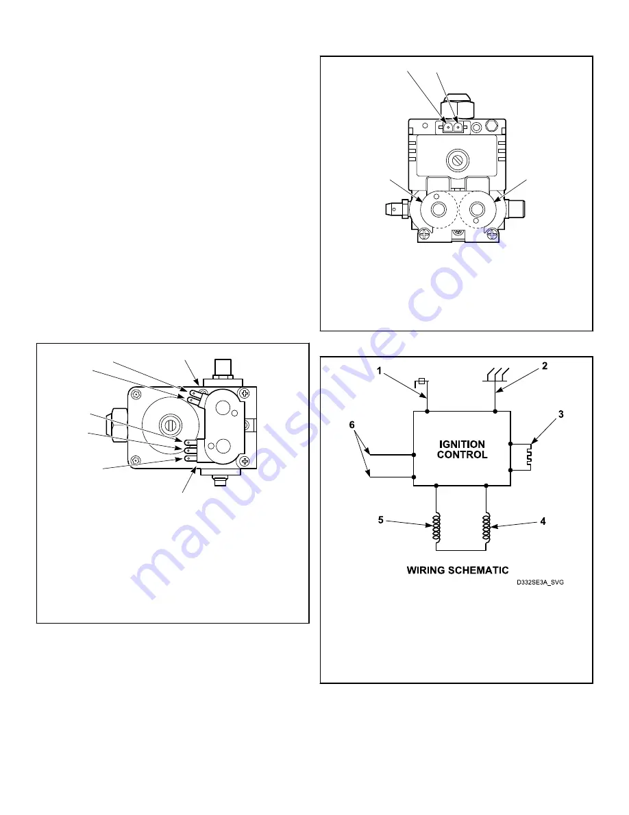
Figure 17
DRY1886S_SVG
11
4
3
2
1.
Terminal 1
2.
Terminal 2
3.
Redundant Coil
4.
Main Coil
Figure 18
1.
Flame Sensor
2.
Ground
3.
Igniter
4.
Redundant Coil
5.
Main Coil
6.
220/240 Volt, 50 Hertz Electrical Supply Line
Figure 19
Electrical Circuit To Ignition System
(Gas Models)
Test Procedures
©
Copyright, Alliance Laundry Systems LLC -
DO NOT COPY or TRANSMIT
60
Part No. D515519R3
Summary of Contents for BD3NGBGS303EW01
Page 2: ......


