3.
Use a strain relief and insert end of power cord through power
supply hole.
D696I_SVG
Figure 8
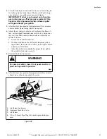
4.
Use the three screws from the accessories bag to attach the
power cord wires to the terminal block. Refer to
Figure 9
.
D286I_SVG
3
2
1
1.
"L1" Terminal
2.
Neutral Terminal
3.
"L2" Terminal
Figure 9
5.
Tighten all screws firmly.
IMPORTANT: Failure to tighten these screws firmly
may result in wire failure at the terminal block.
6.
Secure the strain relief to the power cord, or wires, where they
enter the dryer cabinet.
7.
Check the continuity of the earth/ground connection before
plugging the cord into an outlet. Use an acceptable indicating
device connected to the center earth/ground pin of the plug
and the green screw on the back of the cabinet.
8.
Reinstall access cover and screw.
Connecting Power Cord with Four-Wire Plug
NOTE: Four-wire cord is required for new branch-cir-
cuit installations, mobile homes or where codes do not
permit grounding through neutral.
DRY2016N_SVG
7
7
7
7
6
3
2
1
4
5
1.
Typical Four-Wire Receptacle
2.
Power Cord – Not Supplied with Dryer
3.
Strain Relief Nut
4.
Strain Relief
5.
0 V.A.C.
6.
240 ± 12 V.A.C.
7.
120 ± 12 V.A.C.
Figure 10
1.
Disconnect power to dryer.
2.
Remove access cover from rear of dryer.
D695I_SVG
Figure 11
3.
Remove the three screws holding the three wires to the termi-
nal block terminals. Save these screws. Loosen the strain re-
lief screw and pull the cord or wires out through the rear of
the dryer.
Installation
16
©
Copyright, Alliance Laundry Systems LLC - DO NOT COPY or TRANSMIT
Part No. 510963R7
Summary of Contents for Dryers
Page 2: ......


