GB
TRANSPORT - MANUTENTION - UNPACKING
The machine must be transported as shown in the figures on the outside of the packing.
Keep all packing (plastic bags, polystyrene foam, nails, screws, metal or plastic straps, etc.) out of reach of
children and dispose of suitably, as they are potential sources of danger and pollution.
INSTALLATION
Unpack the machine and check that it is intact.
Open the doors using the relative key and remove the screws fixing the machine to the pallet. Position the mangle
adequately lighted room with an ambient temperature included from +10°C and +40°C. Place the machine on a
flat surface (minimum capacity 500 kg/m²) using the adjustable feet to be found on the bottom of the side panels
to ensure that it is stable and level.
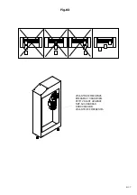
For a correct use and operation, as well as for an easy maintenance, leave a free space around the mangle as
shown in figure n. 01.
ELECTRICAL CONNECTION
Electrical connections must be carried out by fully qualified electricians.
Check that the supply voltage corresponds to that indicated on the rating plate, which is situated on the rear of the
machine to the right.
To ensure safe connection to the mains supply use a cable as specified in the enclosed wiring diagram and an
automatic cut-out protective device (differential magnetothermal switch Idn = 0.03 A). The differential
magnetothermal switch must have characteristics of section and insulation complying with Europeans norms EN
60947-2 e EN 60947-3 and must be adequated to the machine absorption (see plate data). This device and the
connecting cable are the responsibility of the user. Earth the ironer through the relative terminal in the electric
panel. The earthing system must comply with legal requirements. The manufacturer cannot be held responsible
should this accident-prevention regulation not be observed.
Ensure that the ironer roller turns clockwise currently
. In the event of incorrect connection, upon pressing
the foot pedal control any excessive reverse rotation activates a microswitch (pos. 27), thus preventing any
mechanical displacement. To neutralize the microswitch, turn the handwheel (see fig. 3) placed under the ironing
plate motor clockwise and invert two phases in the supply terminals. Disconnect the machine from the power
supply before carrying out this operation. Failure to observe these instructions may put the mechanical parts out
of phase.
When the on/off switch is in position 0, the supply terminals remain live.
INTENDED USE
The IPSO range of roller ironers has been designed for ironing flat linen. Any other use is to be considered
incorrect and therefore unreasonable. The manufacturer cannot be held liable for any damage to things or injury to
persons caused by improper, incorrect or unreasonable use.
THE MANUFACTURER CANNOT BE HELD LIABLE SHOULD THE IRONER BE TAMPERED WITH OR
MODIFIED BY UNAUTHORISED PERSONS.
OPERATION
1. Switch on the main switch (B) situated on the slide for linen, turning it to position 1.
2. Push the switch START (I) to activate the control circuit.
3. Adjust the temperature using the rotor on control panel. The yellow warning light will remain on for a few
minutes until the set temperature is reached.
4. With the help of the feed-in wooden table, place the item to be ironed on the roller.
5. Press the foot pedal control, to be found along the whole length of the machine, in order to activate the roller
rotation and start work.
6. At the end of the ironing session, push the red switch STOP (0). The ironer remains idle.
Subsequently put the main switch to position 0.
12/37


