General
1 - 6
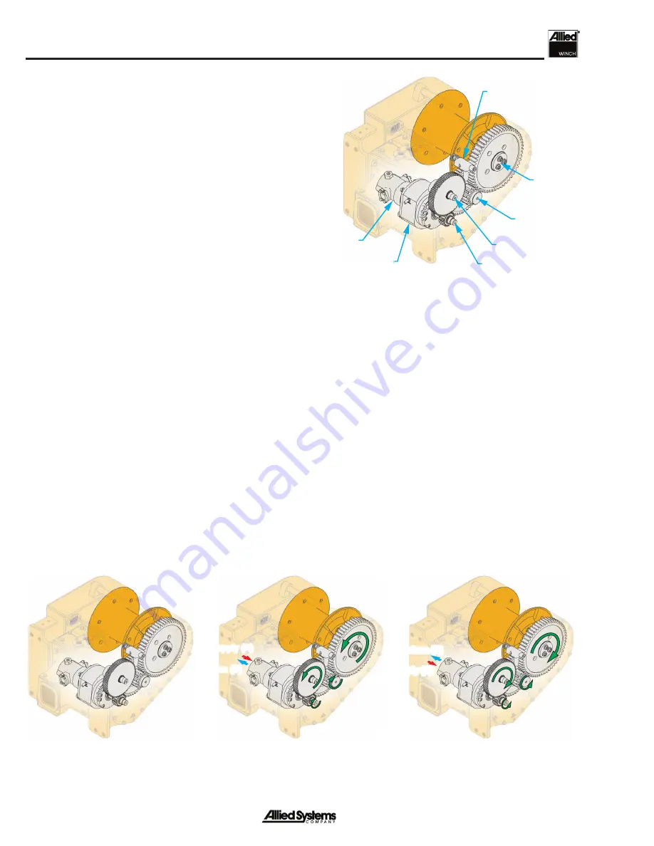
Figure 1-9 Rotation Torque Transfer
Figure 1-8 Gear Train
Motor Shaft
Idler Shaft
Intermediate
Shaft
Drum
Shaft
Hydraulic
Motor
Brake
Freespool Fork
BRAKE-ON
LINE-IN
LINE-OUT
Oil Supply (A)
Oil Return (B)
Oil Return (A)
Oil Supply (B)
Gear Train (See Fig. 1-8)
The tractor pump or designated winch pump drives the
hydraulic motor with hydraulic oil supply. The amount of
pressure in the motor is dependent on the size of the load.
The motor shaft rotates to give
LINE-IN
or
LINE-OUT
.
Return oil is directed back to the tractor reservoir in open
loop systems and back to the pump in hydrostatic closed
loop systems. The motor is attached to a spring applied
multi-disc brake that holds the winch drum in a fi xed posi-
tion. When oil is supplied to the hydraulic motor, the brake
is simultaneously released with pilot control pressure.
The hydraulic motor can operate at half displacement
when the operator selects the
HI-SPEED
switch. At half
displacement the gear train rotates at roughly twice the
speed.
An intermediate gear assembly gives further gear reduc-
tion to increase torque at the winch drum. A spring-loaded
dental clutch with splines engages the drum pinion gear
and the intermediate gear. The operator can disengage
the dental clutch with an electric switch to activate the
FREESPOOL
feature.
A drum gear engages the drum pinion gear and is con-
nected to the drum adapter (which connects the drum to
the drum gear). When power is applied to the gear train,
the drum will rotate in the forward or reverse direction. The
other side of the drum runs on roller bearings held by the
drum shaft. The drum shaft is connected to the winch case.
Summary of Contents for H5C Series
Page 8: ...vi Notes...
Page 48: ...General 1 40 Notes...
Page 59: ...Troubleshooting 2 6 Notes...
Page 77: ...Service 3 18 Notes...
Page 86: ...Section 4 4 9 Intentionally Blank...
Page 104: ...Section 4 4 27 Intentionally Blank...
Page 108: ......


