Section 4
4 - 31
9.
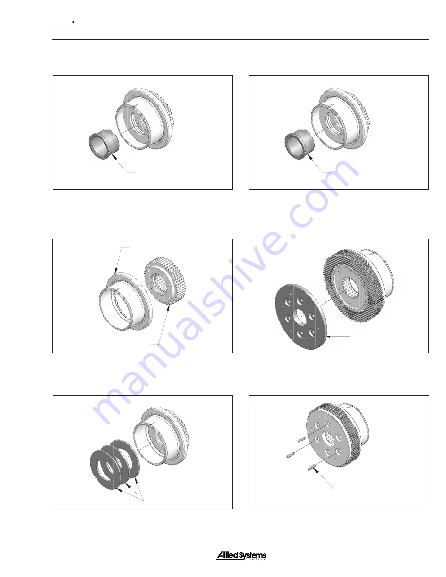
Remove retainer noting the number of turns required
for removal.
PIN
CLUTCH PLATE
SPRING RETAINER
SPRINGS
CLUTCH HUB
PRESSURE PLATE
10. Disassemble clutch.
11. Assemble hub & pressure plate.
12. Install springs in series so that they oppose each
other.
13. Install retainer to height “D”. (use the number of turns
required for removal & align marks on teeth).
SPRING RETAINER
14. Install frictions, separators, & clutch plate.
15. Insert pins into three equally spaced holes.
Summary of Contents for H6H
Page 3: ......
Page 9: ...vi Notes...
Page 49: ...General 1 40 Notes...
Page 65: ...General 1 56 Notes Notes...
Page 71: ...Troubleshooting 2 6 Notes...
Page 78: ...Section 3 3 7 Notes...
Page 79: ...Service 3 8 Notes...
Page 84: ...Section 4 4 5 Intentionally Blank...
Page 92: ...Section 4 4 13 7 Remove the counterbalance relief manifold...
Page 96: ...Section 4 4 17 Intentionally Blank...
Page 98: ...Section 4 4 19 7 Separate the clutch hub and the pressure plate CLUTCH HUB PRESSURE PLATE...
Page 102: ...Section 4 4 23 Intentionally Blank...
Page 112: ...Section 4 4 33 Intentionally Blank...
Page 126: ...Section 4 4 47 Intentionally Blank...
Page 132: ...Section 4 4 53 Notes...


