Section 4
4 - 51
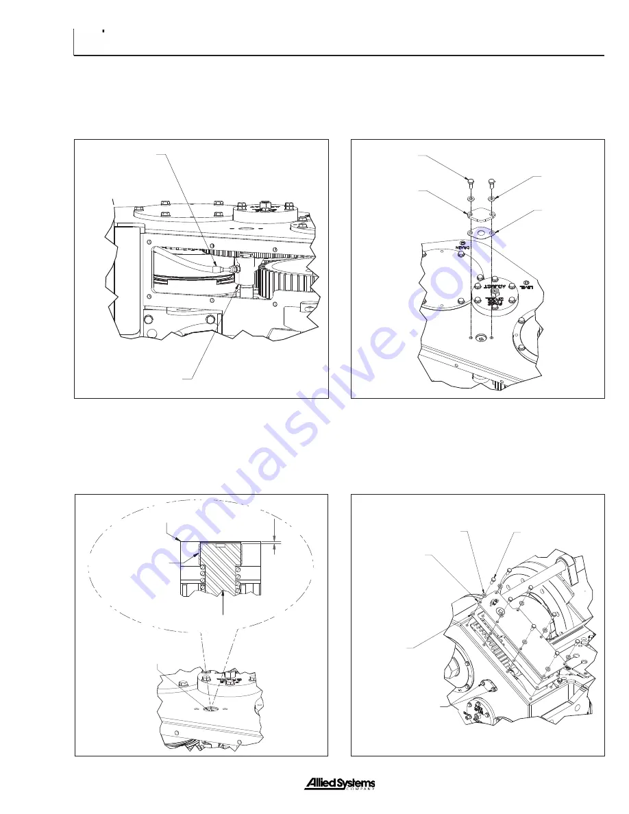
11. Install hose assembly.
Hose Assembly
Freespool Shifter Fork
(REF.)
12. Apply adhesive-sealant to threads of FREESPOOL
shaft. Adjust for proper engagement and
disengagement of intermediate shaft gear. Nominal
adjustment should be recessed so two frame threads
are exposed in frame.
Tighten These to
75 ft-lbs (10 kg-m)
Gasket
Right-Hand
Top Cover
Washer
Capscrew
Gasket
Cover
Washer
Capscrew
13. Secure the cover and the gasket with washers and
capscrews.
14. Install right-hand top cover with gasket, washers and
capscrews. Tighten the two capscrews mentioned in
Step 13 to 75 ft-lbs (10 kg-m).
FREESPOOL Shaft
Winch Frame
FREESPOOL Shaft
Two Threads
Apply Adhesive Sealant
to Shaft Threads
Summary of Contents for H6H
Page 3: ......
Page 9: ...vi Notes...
Page 49: ...General 1 40 Notes...
Page 65: ...General 1 56 Notes Notes...
Page 71: ...Troubleshooting 2 6 Notes...
Page 78: ...Section 3 3 7 Notes...
Page 79: ...Service 3 8 Notes...
Page 84: ...Section 4 4 5 Intentionally Blank...
Page 92: ...Section 4 4 13 7 Remove the counterbalance relief manifold...
Page 96: ...Section 4 4 17 Intentionally Blank...
Page 98: ...Section 4 4 19 7 Separate the clutch hub and the pressure plate CLUTCH HUB PRESSURE PLATE...
Page 102: ...Section 4 4 23 Intentionally Blank...
Page 112: ...Section 4 4 33 Intentionally Blank...
Page 126: ...Section 4 4 47 Intentionally Blank...
Page 132: ...Section 4 4 53 Notes...


