Service
3 - 4
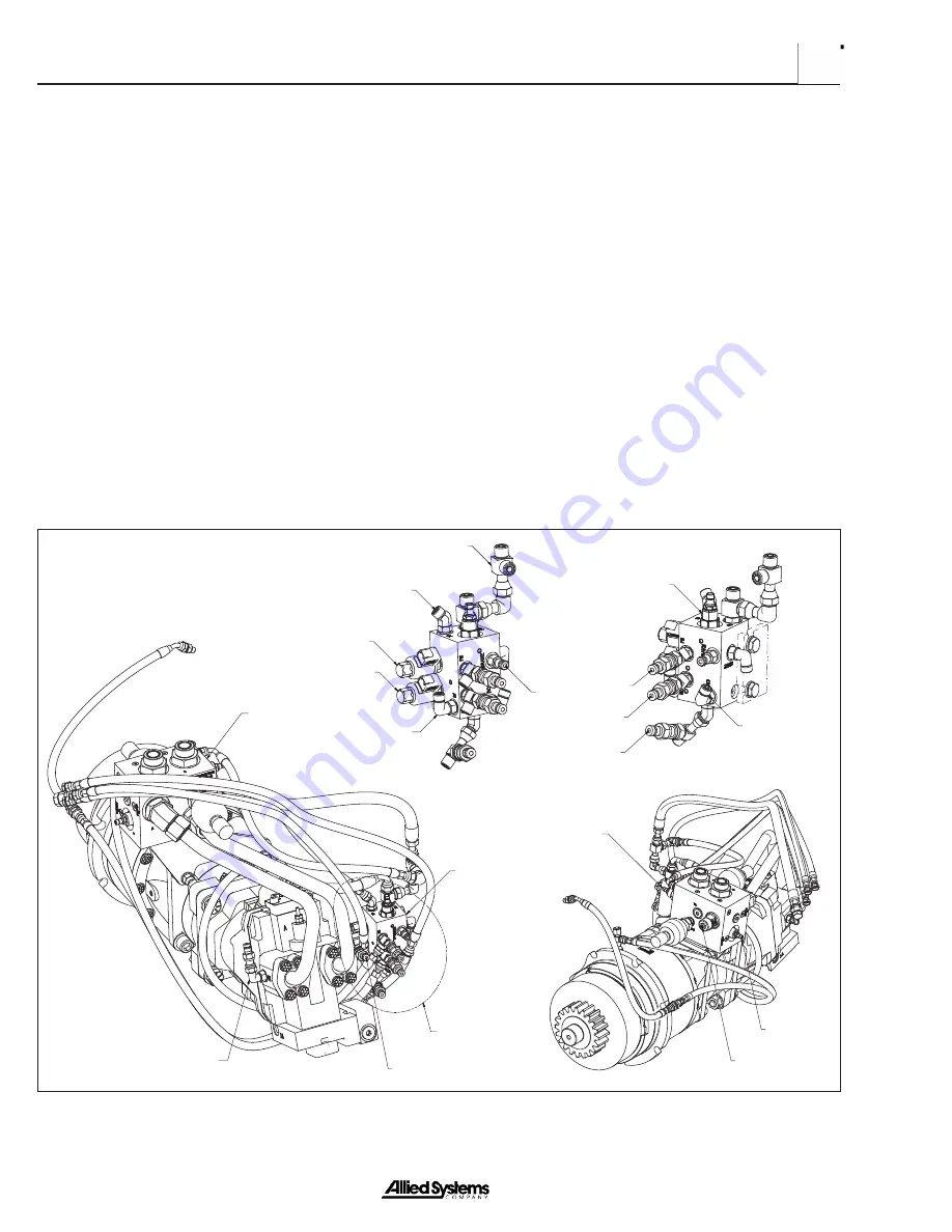
LOGIC MANIFOLD DETAIL VIEWS
(HOSES NOT SHOWN FOR CLARITY)
SEE LOGIC MANIFOLD
DETAIL VIEWS
FREESPOOL SOLENOID
BRAKE-OFF SOLENOID
LOGIC CONTROL MANIFOLD
DRAIN (PD)
(X1)
BRAKE
MOTOR B
MOTOR A
PILOT SUPPLY/PRESSURE (PP)
COUNTER BALANCE/
RELIEF MANIFOLD
BRAKE VALVE
REEL-IN (RI)
REEL-OUT (RO)
FREESPOOL
BRAKE-OFF
RELIEF VALVE (A TO B)
CONTROL
BALANCE VALVE
RELIEF
VALVE (B TO A)
Brake Valve Adjustment:
1. Slowly meter the control lever into the
LINE-IN
position.
2.
Measure pressure at BR and XI pressure test ports.
3. Loosen brake valve locknut. Turn adjusting capscrew
OUT to decrease pressure and IN to increase
pressure. Adjust pressures as shown in Figure 3-5.
FREESPOOL Pressure Check
With the engine shut off, connect a 1000 psi pressure
gauge on the
FREESPOOL
pressure and
BRAKE-OFF
test ports. Start the engine and measure pressures
with the
FREESPOOL
switch activated.
FREESPOOL
mode simultaneously sends
pilot pressures to the
FREESPOOL
shifter fork and the BRAKE-OFF clutch.
The
FREESPOOL
shift fork will shift at a minimum of 170
psi. However, the added features of
BRAKE-OFF
mode
will not be active at this pressure. All pressures should
be as specified in Figure 3-5.
If pressures are not as specified in Figure 3-5, check for:
1.
Improper pilot supply pressure
2.
Malfunctioning solenoid valve.
3.
Leaking pressure hoses or fittings
4. Restriction in pressure hose or manifold port
BRAKE-OFF Pressure Check
With the engine shut off, connect a 1000 psi pressure
gauge to the
BRAKE-OFF
pressure test port. Start the
engine and measure pressure with the
BRAKE-OFF
switch activated. All pressures should be as specified in
Figure 3-5.
Figure 3-4 Hydraulic Pressure Test Ports (some items removed for clarity)
Summary of Contents for H6H
Page 3: ......
Page 9: ...vi Notes...
Page 49: ...General 1 40 Notes...
Page 65: ...General 1 56 Notes Notes...
Page 71: ...Troubleshooting 2 6 Notes...
Page 78: ...Section 3 3 7 Notes...
Page 79: ...Service 3 8 Notes...
Page 84: ...Section 4 4 5 Intentionally Blank...
Page 92: ...Section 4 4 13 7 Remove the counterbalance relief manifold...
Page 96: ...Section 4 4 17 Intentionally Blank...
Page 98: ...Section 4 4 19 7 Separate the clutch hub and the pressure plate CLUTCH HUB PRESSURE PLATE...
Page 102: ...Section 4 4 23 Intentionally Blank...
Page 112: ...Section 4 4 33 Intentionally Blank...
Page 126: ...Section 4 4 47 Intentionally Blank...
Page 132: ...Section 4 4 53 Notes...


