18
45-074, REV. 5/18
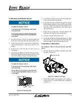
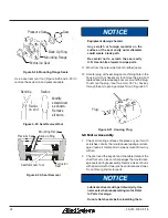
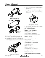
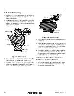
7. Remove the output shaft assembly. (Figure 5-11)
Bearing
Bearing
Snap Ring
Output Shaft
Worm Gear
Shim
Spacer
Figure 5-11, Output Shaft
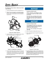
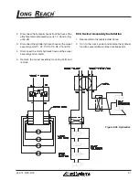
8. The output shaft fits tightly, so you may need to remove
the cap on the back of the gearbox and lightly tap the
end of the output shaft with a rubber mallet to remove
it. (Figure 5-12)
Cap
Figure 5-12, Output Shaft Cap
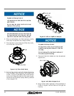
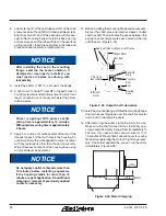
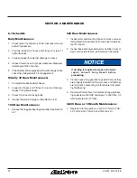
9. Remove the end cap and motor adapter. Make note
of any installed shims. Capscrews are installed with
Loctite, so use a long handle wrench to break them
loose. (Figure 5-13)
Capscrew
Capscrew
O-Ring
O-Ring
Motor Adapter
End Cap
Shim
Shim
Shim
Coupling
Figure 5-13, End Cap / Motor Adapter
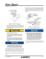
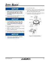
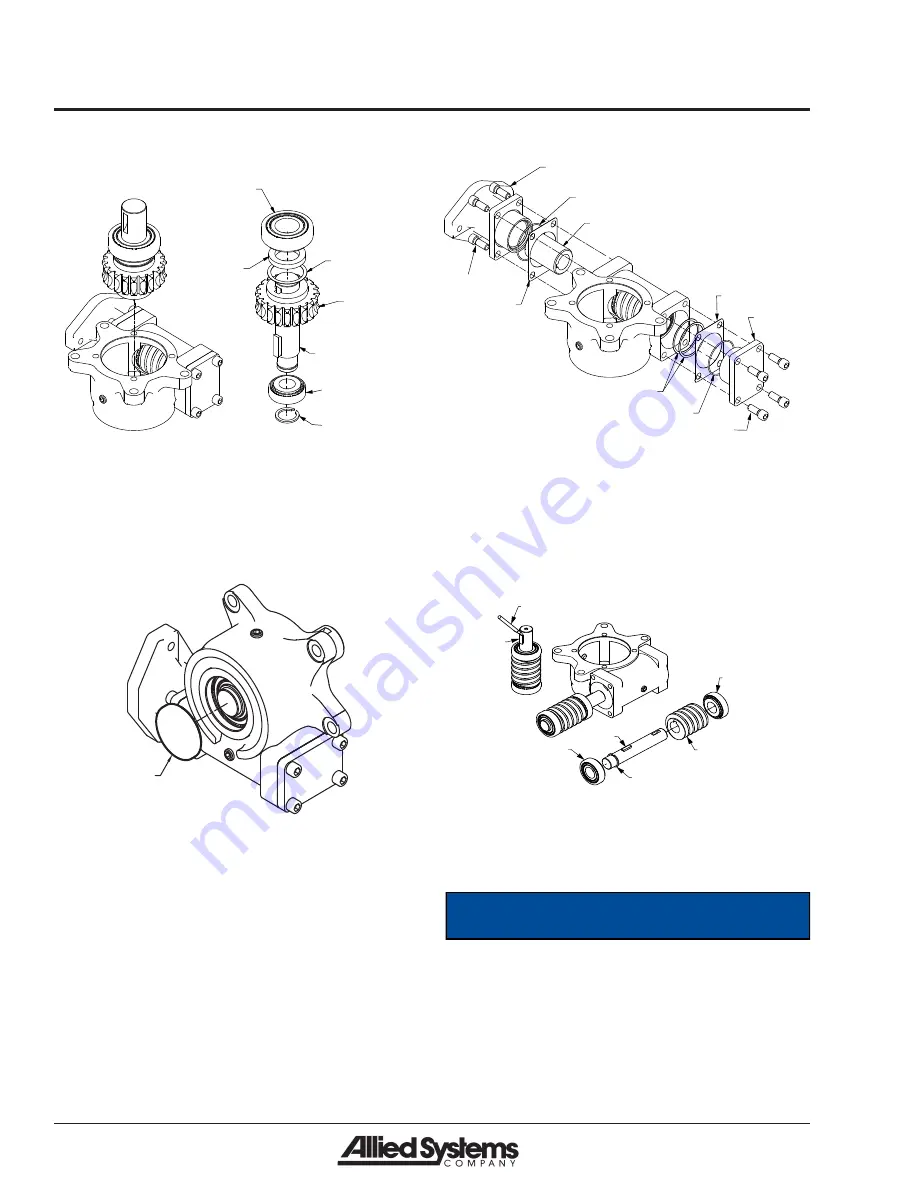
10. Remove the input shaft assembly. The assembly fits
tightly, so use a rubber mallet or press on the extend-
ed shaft to remove it. Remove the exposed key with a
screwdriver, allowing the bearing and worm to slide
off of the shaft. (Figure 5-14)
Screwdriver
Key
Bearing
Snap Ring
Key
Worm
Bearing
Figure 5-14, Input Shaft
11. Reassemble in reverse order. Use Loctite (Blue) on all
capscrews. (See Section 6 for Torque Specifications)
NOTICE
It is important to get oil to the worm and
worm bearings. Before reinstalling, dip the
worm and worm bearings in oil for proper
lubrication. (See Section 5.3)

