19
45-074, REV. 5/18
Part Number: YGC-48, YGC-49, YGC-49-LH, YGC-50
And YGC-50-LH
1. Remove the attachment from truck. (See Section 5.1)
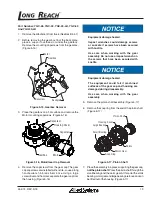
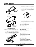
2. Before removing the gearbox from the back plate,
place a support overhead or under the gearbox.
Remove the mounting capscrews from the gearbox.
(Figure 5-15)
Motor
Gearbox
Backplate
Capscrew
Figure 5-15, Gearbox Removal
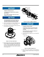
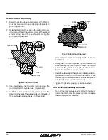
3. Place the gearbox on a flat surface and remove the
Motor mounting capscrews. (Figure 5-16)
Gearbox
Capscrew
Motor
Capscrew
Housing Cover
Figure 5-16, Motor/Gear Cap Removal
4. Remove the capscrews from the gear cap. The gear
cap capscrews are installed with Loctite, so use a long
handle wrench to break them loose. Using a large
screwdriver and hammer, separate the gear cap from
the housing. (Figure 5-16)
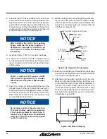
Equipment damage hazard.
Impact wrenches could damage screws
or sockets if screws have been secured
with Loctite.
Use care when working with the gear
assembly. Do not use a impact wrench on
the screws that have been secured with
Loctite.
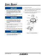
Equipment damage hazard.
The equipment could fail if machined
surfaces of the gear cap and housing are
damaged during disassembly.
Use care when working with the gear
assembly.
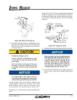
5. Remove the pinion shaft assembly. (Figure 5-17)
6. Remove the snap ring from the end of the pinion shaft.
(Figure 5-17)
Housing Cover
Shims
Large Bearing
Worm Gear
Small Bearing
Pinion Shaft
Snap Ring
Figure 5-17, Pinion Shaft
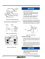
7. Place the assembly in a press supporting the gear cap,
not the pinion shaft
. Press the pinion shaft through the
small bearing and the worm gear. At this point the small
bearing, worm gear and large bearing are loose and can
be lifted out of the housing. (Figure 5-17)

