29
45-074, REV. 5/18
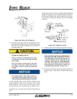
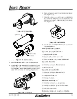
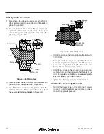
Figure 5-41, Cylinder Vise
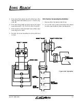
Cylinder Tube
Gland Cap
Rod Assembly
Figure 5-42, Rod Assembly
4. Remove the rod assembly from the cylinder tube.
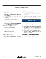
5. Clamp the rod assembly in a soft jawed vise on the
wrench flats, not on the rod surface. If the rod does
not have wrench flats use two pieces of wood on both
sides of the rod to prevent scaring. (Figure 5-43)
Figure 5-43, Piston Rod
6. Remove the piston retaining nut and remove the pis-
ton. (Figure 5-40)
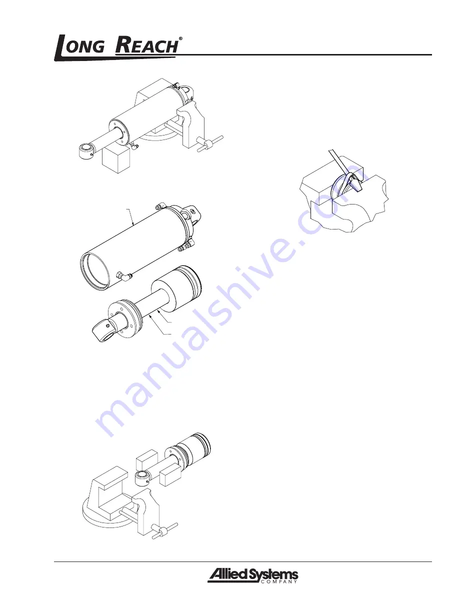
7. Carefully pry up on the piston seals using a blunt
tip screwdriver being careful not to scratch the seal
grooves. Cut the seals to remove them from the pis-
ton. (Figure 5-44)
Figure 5-44, Seal Removal
8. Use the same procedure as above to remove the seals
from the gland cap.
5.12 Cylinder Inspection
Inspect the Cylinder Tube bore for:
1. Deep scratches or nicks
2. Signs of galling or excessive wear.
3. Out-of-roundness or deformities of the barrel.
Inspect the Piston for:
1. Scratches or nicks on the seal grooves.
2. Wear on the O.D.
Inspect the Cylinder Rod for:
1. Scratches or nicks on the rod surface.
2. Straightness of the rod.
3. Damaged threads.
Inspect the Gland Cap for:
1. Scratches or nicks in the seal grooves.
2. Damaged threads or spanner wrench holes.
3. Excessive wear in bore.
Replace any component found to be defective.

