background image

45-008  REV. 1/22

21

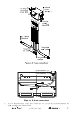
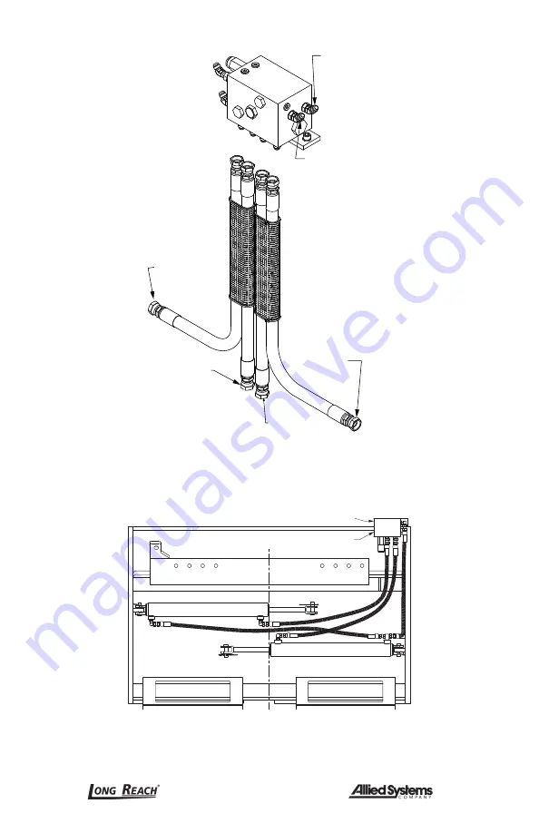
To cylinder

base end

To cylinder

base end

C4

C3

C2

C1

To cylinder 

rod end

To cylinder

rod end

To truck 

supply 

(close) V1

To truck 

supply 

(open) V2

V3

V4

To truck 

secondary

(side shift)

Figure 4-9, Hose connections

Open Forks Port V2

Close Forks Port V1

Right Hand Termination (Standard)

Figure 4-10, Hose connections

4.  Inspect installation to make sure hoses are not kinked or pinched between the 

truck carriage and attachment.

Summary of Contents for Long Reach QHGC

Page 1: ...REV 1 22 45 008 Installation Maintenance and Service Manual QHSA QHSB QHSC QHGC End Hold Down...

Page 2: ...ntenance Warnings 9 3 12 Load Handling 10 3 13 Load Positioning 11 3 14 Operator s Controls 12 3 15 Industry Standards 13 3 16 Clamp Open Control 13 SECTION 4 INSTALLATION PROCE DURE 15 4 1 Truck Requ...

Page 3: ...upper left corner on the body Record the information from the nameplate along with the date received at the bottom of this page If the nameplate is missing look for the serial number stamped directly...

Page 4: ...ON Design Specific Designator HOLD DOWN ARMS E 14 46 Hold Down Range Each attachment is identified by a model number and a serial number located on the nameplate attached to the unit prior to shipment...

Page 5: ...Long Reach attachment It s your responsibility to see that they are carried out 3 2 Safety Regulations Know your company s safety rules Some companies have site specific directions and procedures The...

Page 6: ...achment If the truck is equipped with front end attachments other than factory installed attachments truck must be marked to identify the attachments and show the approximate weight of the truck and a...

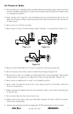
Page 7: ...tachment or its load to support a man carrying device Never allow anyone under a load or under the carriage Figure 3 2 Never stand in front of or beside an attachment that is being operated Never allo...

Page 8: ...riage 3 8 Operation Warnings You must be trained to operate this equipment prior to operation Be extremely careful if you do not normally operate this machine Reorient yourself to the machine before s...

Page 9: ...your company s requirements Do not attempt to make adjustments or perform maintenance or service unless you are authorized and qualified to do so Include attachments in a scheduled maintenance and in...

Page 10: ...eight of any equipment to be lifted 3 12 Load Handling Treat an unloaded forklift with an attachment as partially loaded Equipment overload hazard Injury or equipment damage may result if the capacity...

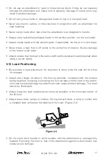
Page 11: ...lways ensure that the load is the same width as the pallet and neatly stacked when using a carton clamp 3 13 Load Positioning Be accurate in load placement It s important to know what the load will do...

Page 12: ...ction Refer to your lift truck manual for more information For clarity the direction of arm movement is shown on the control handle To move the arms in the direction shown pull the handle towards the...

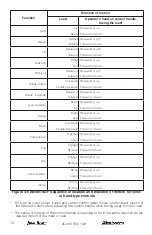
Page 13: ...preferably according to the recommendations in Figure 3 6 When a function is controlled by a pair of push buttons they should operate in the same sense as the lever controls For example pushing a but...

Page 14: ...ft Rearward or up Forward or down Slope Clockwise Counterclockwise Rearward or up Forward or down Fork position Together Apart Rearward or up Forward or down Trip Engage Release Rearward or up Forward...

Page 15: ...t arrange installation of the required valving at the truck factory The attachment model description found on your shipped invoice will state the following truck requirements flow gpm psi and minimum...

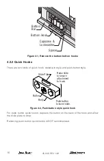
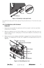
Page 16: ...nds of quick hook detent pin style and push button style Button Slide Plate Body Push button to lower slide Raise slide to secure attachment to truck Figure 4 2 Push button style quick hook For push b...

Page 17: ...tilted forward about 4 degrees 2 Place the midplate onto the ITA bar Make sure it is seated all the way down on the bar Make sure the locking lug is in the notch closest to the center of the truck s...

Page 18: ...left hand sides of the attachment They are a loose fit and do not need to face a particular direction Bottom Bar Bottom Hook Spacer Lower Roller Assembly Fork Base Capscrew Lockwasher Figure 4 5 Lower...

Page 19: ...nough install shims between the attachment and the body of the quick hooks 5 To ensure proper locking of the slide plate use a screwdriver to try to pry down the slide plate If the slide plate is not...

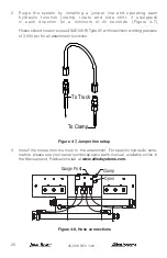
Page 20: ...t or exceed SAE100 RI Type AT with maximum working pressure of 3 000 psi for all attachment functions To Truck To Clamp Figure 4 7 Jumper line setup 3 Install the hoses from the truck to the attachmen...

Page 21: ...uck supply close V1 To truck supply open V2 V3 V4 To truck secondary side shift Figure 4 9 Hose connections Open Forks Port V2 Close Forks Port V1 Right Hand Termination Standard Figure 4 10 Hose conn...

Page 22: ...eservoir level is at the recommended level 7 Before placing the attachment in operation check the following A Inspect all hoses and fittings for leaks and routing clearance Be sure to include clearanc...

Page 23: ...he hose is not cut too short for proper installation Cut the hose to the desired length using a fine toothed hacksaw or hose cutoff machine Hose Insertion Depth Hose Size Screw hose in to No 4 1 in 25...

Page 24: ...t NOTICE Inspect the hose for proper assembly Look inside the fitting for hose material that might prevent free flow Use compressed air to clear the hose of debris If the hose is damaged remove the fi...

Page 25: ...eck all hoses and fittings for wear or damage Inspect for hydraulic leaks 3 Check for loose or missing bolts 4 On the bronze top hooks and the pin weldment check grease fittings to ensure that they ar...

Page 26: ...5 ft lbs 1 4 12 5 ft lbs 5 16 23 5 16 16 5 16 26 3 8 40 3 8 28 3 8 46 7 16 63 7 16 45 7 16 74 1 2 96 1 2 68 1 2 115 9 16 140 9 16 98 9 16 160 5 8 195 5 8 140 5 8 215 3 4 340 3 4 240 3 4 385 7 8 550 7...

Page 27: ...45 008 REV 1 22 27 THIS PAGE WAS INTENTIONALLY LEFT BLANK...

Page 28: ...alliedsystems com 21433 Oregon Street Sherwood OR 97140 USA Phone 800 285 7000 Fax 800 231 3273 Find the latest version of your complete parts documentation in the Manuals and Publications tab at www...

Reviews: