34
Control Cable Adjustments
A single control cable connects the power control lever to
the hydraulic control valve spool. Check the operation of
the power control lever to make sure it moves smoothly
and will return to the
BRAKE-ON
position. The power
control lever will stay in
BRAKE-OFF
when pushed into
DETENTED position. Cable adjustment is not necessary
except to ensure full spool travel. To adjust control levers
depicted in Figures 14 and 15, proceed as follows:
1.
Ensure that the cable bracket at winch end of control
cable is securely attached to the winch housing.
2.
Check the position of the control lever with
control valve in
BRAKE-ON
. The lever should be
approximately vertical. If not, loosen nuts on U-Bolt
that clamps the control cable to the control lever
housing. Move U-Bolt up or down the elongated
slots to improve position of control lever. Tighten nuts
securely.
3.
Move control lever to
LINE-IN
and
BRAKE-OFF
positions and ensure that the lever holds in the
BRAKE-OFF
position. Check to ensure that the
control lever does not hit the housing in either
position. If interference is found, repeat step 2.
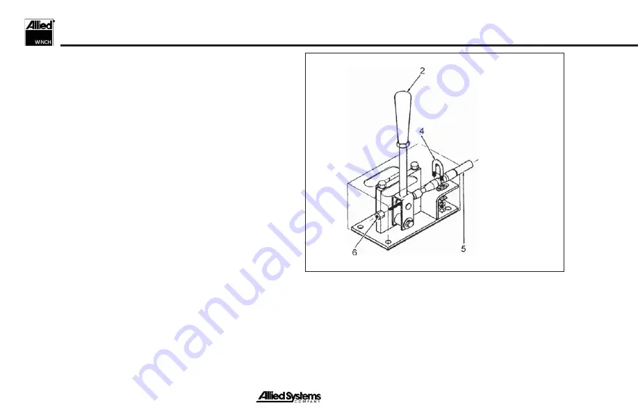
Figure 14 Control Cable Adjustments
2.
Power Control Lever
4. U-Bolt
5.
Power Control Cable
6. Lock
Nut
To adjust the control lever depicted in Figure 16, proceed
as follows:
1.
Adjust control lever position so full valve spool stroke
is attained by screwing cable in or out of tall nut.
Summary of Contents for W12E
Page 13: ...xi Safety Summary Notes...
Page 14: ...xii Notes...
Page 37: ...23 Figure 10 Operator Electronic Controls Operation Electronic Controls...
Page 51: ...37 Intentionally Blank Maintenance...
Page 55: ...41 Operating Techniques Power Controls Intentionally Blank...
Page 59: ...45 Operating Techniques Electronic Controls Intentionally Blank...
Page 65: ...51 Operating Techniques General Intentionally Blank...
Page 68: ...54 Notes...
Page 69: ......


