OSPF Configuration
©2008 Allied Telesis Inc. All rights reserved.
Software Version 5.2.1
AlliedWare Plus
TM
Operating System Software Reference C613-50003-00 REV E
29.11
Configuring Virtual Links
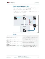
Virtual links are used to connect a disjointed non-backbone area to the backbone area, or to
repair a non-contiguous backbone area. In this example, the OSPF routers shown represent
any Allied Telesis managed Layer 3 switches or Allied Telesis routers.
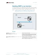
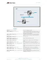
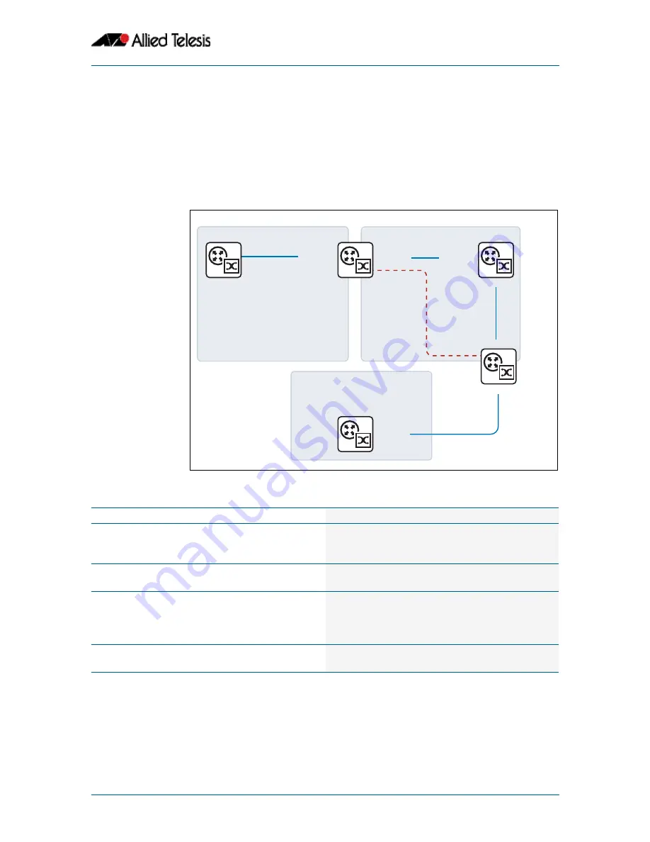
In the network below, there is no area border router that connects Area2 to the backbone. So
a virtual link needs to be created between ABR Device 1 and ABR Device 2 to connect
Area
2
to
Area 0.
Area 1 is used as a transit area.
Device 1
ospf_6
Device 4
Area 0
Device 1
10.10.22.0/24
10.10.21.0/24
10.10.22.0/24
Device 6
Device 5
Device 2
10.10.23.0/24
10.10.23.0/24
10.10.24.0/24
10.10.24.0/24
Area 2
Area 1
Virtual
Link
Area Border
Router
Area Border
Router
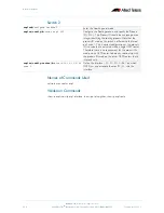
awplus#
configure terminal
Enter the
Configure
mode.
awplus(config)#
router ospf 100
Configure the Routing process and specify the Process ID
(
100
). The Process ID should be a unique positive
integer identifying the routing process.
awplus(config-router)#
ospf router-id
10.10.21.1
Configure OSPF Router ID (
10.10.21.1
) for this
router.
awplus(config-router)#
network 10.10.21.0/
24 area 0
awplus(config-router)#
network 10.10.22.0/
24 area 1
Define interfaces on which OSPF runs and associate the
area IDs
(0 and 1)
with the interface.
awplus(config-router)#
area 1 virtual-link
10.10.23.2
Configure a virtual link between this router R1 and R2
(Router ID
10.10.23.2
) through transit area 1.

