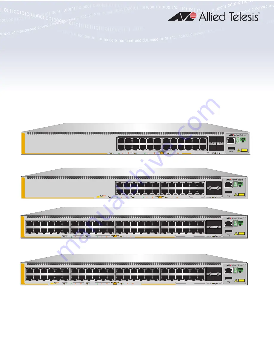
background image

613-002659 Rev. D

x530 Series

Stackable Gigabit Layer 3+ Ethernet Switches

AlliedWare Plus™ v5.4.9-2

AT

-

x530

-

28GTXm

AT

-

x530

-

28GPXm

AT-x530-52GTXm
AT-x530-52GPXm

Installation Guide for Stand-alone

Switches

3

5

1

7

9

11

13

15

17

19

21

23

27/S1

28/S2

25

SFP+

26

A

T-x530-28GTXm 

16

18

20

14

10G

/

1G

CLASS 1

LASER PRODUCT

CONSOLE

4

6

8

10

12

2

22

24

FDX

HDX           COL

1G LINK

ACT

100 LINK

ACT

5G/2.5G/1G LINK

ACT

100 LINK

ACT

PORTS 21-24

PORTS 1-20

5G/2.5G/1G/100

3

5

1

7

9

11

13

15

17

19

21

23

27/S1

28/S2

25

SFP+

26

A

T-x530-28GPXm 

16

18

20

14

10G

/

1G

CLASS 1

LASER PRODUCT

CONSOLE

4

6

8

10

12

2

22

24

PD ON

PD ERR

MAX CURRENT

5G/2.5G/1G/100

1G LINK

ACT

100 LINK

ACT

5G/2.5G/1G LINK

ACT

100 LINK

ACT

PORTS 21-24

PORTS 1-20

4561

51/S1

52/S2

49

SFP+

50

3

5

1

7

9

11

13

15

17

19

21

23

4

6

8

10

12

2

16

18

20

14

22

24

27

29

25

31

33

35

37

39

41

43

45

47

28

30

32

34

36

26

40

42

44

38

46

48

CLASS 1

LASER PRODUCT

CONSOLE

10G

/

1G

A

T-x530-52GTXm

FDX

HDX           COL

1G LINK

ACT

100 LINK

ACT

5G/2.5G/1G LINK

ACT

100 LINK

ACT

PORTS 41-48

PORTS 1-40

5G/2.5G/1G/100

51/S1

52/S2

49

SFP+

50

3

5

1

7

9

11

13

15

17

19

21

23

4

6

8

10

12

2

16

18

20

14

22

24

27

29

25

31

33

35

37

39

41

43

45

47

28

30

32

34

36

26

40

42

44

38

46

48

CLASS 1

LASER PRODUCT

CONSOLE

10G

/

1G

A

T-x530-52GPXm

1G LINK

ACT

100 LINK

ACT

5G/2.5G/1G LINK

ACT

100 LINK

ACT

PORTS 41-48

PD ON

PD ERR

MAX CURRENT

5G/2.5G/1G/100

PORTS 1-40

Summary of Contents for AlliedWare Plus AT-x530 Series

Page 1: ...22 24 PD ON PD ERR MAX CURRENT 5G 2 5G 1G 100 1G LINK ACT 100 LINK ACT 5G 2 5G 1G LINK ACT 100 LINK ACT PORTS 21 24 PORTS 1 20 4561 51 S1 52 S2 49 SFP 50 3 5 1 7 9 11 13 15 17 19 21 23 4 6 8 10 12 2 1...

Page 2: ...ir respective owners Allied Telesis Inc reserves the right to make changes in specifications and other information contained in this document without prior written notice The information provided here...

Page 3: ...es uses and can radiate radio frequency energy and if not installed and used in accordance with this instruction manual may cause harmful interference to radio communications Operation of this equipme...

Page 4: ...ed into multiple languages in the Translated Safety Statements document at www alliedtelesis com library Remarque Les consignes de s curit portant le symbole sont traduites dans plusieurs langues dans...

Page 5: ...and AT x530 52GTXm 28 AT x530 28GPXm and AT x530 52GPXm 31 Power Over Ethernet 34 PoE Standards 34 Powered Device Classes 35 Power Budget 35 Port Prioritization 35 Wiring Implementation 36 SFP Transce...

Page 6: ...r Stacking Status of the Switch 92 Starting a Local Management Session 93 Disabling the VCStack Feature 95 Saving Your Changes and Rebooting the Switch 97 Specifying Ports in the Command Line Interfac...

Page 7: ...re 25 Positioning the AT x530 28GPXm or AT x530 52GPXm Switch on the Wall 67 Figure 26 Switch on the Wall with a Plywood Base 71 Figure 27 Installing the Plywood Base to the Wall 72 Figure 28 Installi...

Page 8: ...itioning the SFP or SFP Handle in the Upright Position 103 Figure 51 Connecting a Fiber Optic Cable to an SFP or SFP Transceiver 103 Figure 52 Installing AT SP10TW Cables 105 Figure 53 RJ 45 Socket Pi...

Page 9: ...wisted Pair Ports 1 24 LED Functions 31 Table 10 AT x530 52GPXm Twisted Pair Ports 1 48 LED Functions 33 Table 11 IEEE Powered Device Classes 35 Table 12 Link and Activity Status LEDs for the 1 Gbps a...

Page 10: ...Tables 10...

Page 11: ...reface contains the following sections Document Conventions on page 12 Contacting Allied Telesis on page 13 Note This guide explains how to install the switches as stand alone units For instructions o...

Page 12: ...tions Note Notes provide additional information Caution Cautions inform you that performing or omitting a specific action may result in equipment damage or loss of data Warning Warnings inform you tha...

Page 13: ...bout Return Merchandise Authorizations RMAs and to contact Allied Telesis technical experts USA and EMEA phone support Select the phone number that best fits your location and customer type Hardware w...

Page 14: ...Preface 14...

Page 15: ...on page 37 eco friendly Button on page 39 VCStack Feature on page 40 Switch ID LED on page 41 USB Port on page 43 Console Port on page 44 Power Supply on page 45 Software and Hardware Releases on pag...

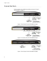
Page 16: ...0 Mbps 4563 3 5 1 7 9 11 13 15 17 19 21 23 27 S1 28 S2 25 SFP 26 AT x530 28GPXm 16 18 20 14 10G 1G CLASS 1 LASER PRODUCT CONSOLE 4 6 8 10 12 2 22 24 PD ON PD ERR MAX CURRENT 5G 2 5G 1G 100 1G LINK ACT...

Page 17: ...FP 50 3 5 1 7 9 11 13 15 17 19 21 23 4 6 8 10 12 2 16 18 20 14 22 24 27 29 25 31 33 35 37 39 41 43 45 47 28 30 32 34 36 26 40 42 44 38 46 48 CLASS 1 LASER PRODUCT CONSOLE 10G 1G AT x530 52GPXm 1G LINK...

Page 18: ...rview 18 Management Panel Figure 6 identifies the components on the management panel Figure 6 Management Panel CLASS 1 LASER PRODUCT CONSOLE 4567 Console eco friendly Button USB Port Switch ID LED Man...

Page 19: ...s switch models come with two pre installed power supplies They are not field replaceable Table 1 Basic Features Feature AT x530 28GTXm AT x530 28GPXm PoE AT x530 52GTXm AT x530 52GPXm PoE 10 Mbps 100...

Page 20: ...operation Yes Yes Ports 1 to 40 support 10 Mbps 100 Mbps and 1 Gbps operation Yes Yes Ports 41 to 48 support 100 Mbps and 1 2 5 5 Gbps operation Yes Yes 100 meters 328 feet maximum operating distance...

Page 21: ...s using multi mode or single mode fiber optic cable AT SPTX transceiver series with RJ 45 connector for twisted pair cable AT SPEX transceivers with a maximum distance of two kilometers with multi mod...

Page 22: ...ir ports on the AT x530 28GTXm and AT x530 52GTXm switches PoE LEDs for the twisted pair ports on the AT x530 28GPXm and AT x530 52GPXm switches Switch ID number LED Installation Options The installat...

Page 23: ...ations Specification Description Port Speed Ports 1 20 10 Mbps 100 Mbps or 1 Gbps Ports 21 24 100 Mbps or 1 2 5 5 Gbps Ports 1 20 Set the port speed manually or with Auto Negotiation at 10 Mbps and 10...

Page 24: ...ort speed is set with Auto Negotiation only at 1 Gbps and higher The default is Auto Negotiation for all ports Duplex Mode Ports 1 20 Full or half duplex mode at 10 Mbps and 100 Mbps Full duplex only...

Page 25: ...he port speed manually or with Auto Negotiation at 10 Mbps and 100 Mbps Ports 41 48 The port speed is set with Auto Negotiation only at 1 Gbps and higher The default is Auto Negotiation for all ports...

Page 26: ...wisted Pair Port Specifications Specification Description Port Speed Ports 1 40 10 Mbps 100 Mbps or 1 Gbps Ports 41 48 100 Mbps or 1 2 5 5 Gbps Ports 1 40 Set the port speed manually or with Auto Nego...

Page 27: ...do not support Auto Negotiation If a network device supports full duplex only a duplex mode mismatch can occur resulting in poor network performance To prevent this disable Auto Negotiation and set t...

Page 28: ...ategory 5 Cat 5e unshielded cabling 10 Gbps ports Standard TIA EIA 568 C compliant Category 6a unshielded cabling LEDs Each twisted pair port has two LEDs that display the port status AT x530 28GTXm a...

Page 29: ...a network device Flashing Green The port is transmitting or receiving data at 1 2 5 5 Gbps 1 24 Solid Amber The port has established a 10 Mbps or 100 Mbps link to a network device Flashing Amber The p...

Page 30: ...lashing Green The port is transmitting or receiving data at 1 2 5 5 Gbps 1 48 Solid Amber The port has established a 10 Mbps or 100 Mbps link to a network device Flashing Amber The port is transmittin...

Page 31: ...s LED Ports State Description L A 1 20 Solid Green The port has established a 1 Gbps link to a network device Flashing Green The port is transmitting or receiving data at 1 Gbps 21 24 Solid Green The...

Page 32: ...the port but is not delivering power to it because doing so would exceed its available power budget Off No PD This LED state can result from the following conditions The port is not connected to a pow...

Page 33: ...f Possible causes of this state are The port has not established a link with another network device The LEDs are turned off To turn on the LEDs use the eco friendly button PoE 1 48 Solid Green PD On T...

Page 34: ...It functions as a central power source for other network devices Devices that receive their power from a PSE are called powered devices PD Examples include wireless access points IP telephones webcams...

Page 35: ...tal power requirements of the power devices is less than the power budget of the switch the switch can supply power to all the devices But if the total power requirements exceed the power budget the s...

Page 36: ...ber in ascending order Power allocation is dynamic Ports supplying power to powered devices can cease power transmission if the switch power budget is at maximum usage and new powered devices connecte...

Page 37: ...SFP Transceiver Ports on page 21 for a description and guidelines of the SFP transceivers SFP or SFP transceivers must be purchased separately For a list of supported transceivers refer to the produc...

Page 38: ...s link to a network device Flashing Green The transceiver is transmitting or receiving data in 10 Gbps Solid Amber The transceiver has established a 1 Gbps link to a network device Flashing Amber The...

Page 39: ...rating the switch in the low power mode does not interfere with the network operations of the device The management software on the switch has a command that blinks the LEDs so that you can quickly an...

Page 40: ...orts Two advantages of stacks are You can manage multiple units simultaneously which can simplify network management You have more flexibility in how you configure some of the features For instance a...

Page 41: ...es 41 Switch ID LED The switch ID LED shown in Figure 10 displays the ID number of the switch A stand alone switch has the ID number 0 Switches in a VCStack have the numbers 1 to 8 Figure 10 Switch ID...

Page 42: ...use the SNMP or the command line management interface to determine the type of fault or faults The switch is booting up The switch has encountered a fault condition The switch is operating as a stand...

Page 43: ...el is used for the following functions Store configuration files on flash drives Restore configuration files to switches that have lost or corrupted settings Configure replacement units by downloading...

Page 44: ...nit The switch does not have to have an IP address for local management To establish a local management session with the switch use the provided management cable to connect a terminal or a computer wi...

Page 45: ...s switches come with dual pre installed AC power supplies Refer to Power Specifications on page 116 for the input voltage ranges Warning The power cord is used as a disconnection device To de energize...

Page 46: ...Hardware Releases Software Version Hardware VCStack v5 4 8 2 AT x530 28GPXm switch AT x530 28GTXm switch Allows stacks of up to four switches using the SFP SFP transceiver ports for the stack trunk v...

Page 47: ...47 Chapter 2 Beginning the Installation The chapter contains the following sections Reviewing Safety Precautions on page 48 Choosing a Site for the Switch on page 52 Unpacking the Switch on page 53...

Page 48: ...onible l adresse www alliedtelesis com library Warning Class 1 Laser product L1 Warning Laser Radiation Class 1M Laser product Warning Do not stare into the laser beam L2 Warning Do not look directly...

Page 49: ...aution Air vents must not be blocked and must have free access to the room ambient air for cooling E6 Warning Operating Temperatures This product is designed for a maximum ambient temperature of 50 C...

Page 50: ...ch that a hazardous condition is not created due to uneven mechanical loading E25 Warning The chassis may be heavy and awkward to lift Allied Telesis recommends that you get assistance when mounting t...

Page 51: ...t not connect to cabling that is routed outside the building where this device is located E40 Warning This product may have multiple AC power cords installed To de energize this equipment disconnect a...

Page 52: ...to the ports on the front of the switch so that you can easily connect and disconnect cables and view the port LEDs The site should allow for adequate air flow around the unit and through the cooling...

Page 53: ...x530 52GTXm or AT x530 52GPXm switch Accessory kit refer to Figure 13 on page 54 Note Retain the original packaging material in case you need to return the unit to Allied Telesis Figure 12 shows the...

Page 54: ...nagement cable with RJ 45 8P8C and DB 9 D sub 9 pin connectors Eight or sixteen screws for attaching the wall equipment rack brackets depending on the model Length 6 0mm 0 2 in Diameter 4 0mm 0 2 in T...

Page 55: ...to avoid injuring yourself or damaging the equipment The switch comes with four bumper feet in the accessory kit The feet which are reusable are used when installing the switch on a table If they are...

Page 56: ...nformation and performed the procedures in Chapter 2 Beginning the Installation on page 47 To install the switch on a table perform the following procedure 1 Place the switch upside down on a table 2...

Page 57: ...oot to the base Refer to Figure 18 Figure 18 Inserting the Rivet into the Bumper Foot 5 Repeat steps 2 to 4 to install the remaining bumper feet 6 Turn the switch over and place it on a flat secure de...

Page 58: ...Chapter 3 Installing the Switch on a Table 58...

Page 59: ...pment Rack This chapter provides instructions for installing the switch in an equipment rack This chapter contains the following sections Beginning the Installation on page 60 Removing the Bumper Feet...

Page 60: ...rews included with the switch Cross head screwdriver not provided Four standard equipment rack screws not provided Switch Orientations in the Equipment Rack The switch has two sets of four screw holes...

Page 61: ...of holes on the switch to install the switch in the equipment rack in a variety of orientations You can install it with the front panel flush with extending in front of or recessed behind the front of...

Page 62: ...ice in an equipment rack If they are already installed perform the following procedure to remove them 1 Place the switch upside down on a level secure surface 2 Use a small flat head screwdriver to pr...

Page 63: ...he switch in a 19 inch equipment rack perform the following procedure 1 Place the switch on a level secure surface 2 Attach the two brackets to the sides of the switch in the selected position using t...

Page 64: ...you secure it using four standard equipment rack screws not provided Refer to Figure 23 Figure 23 Installing the Switch in an Equipment Rack 4 Install the other switches of the stack 5 After installi...

Page 65: ...listed here Switch Orientations on a Wall on page 66 Installation Guidelines on page 68 Plywood Base for a Wall with Wooden Studs on page 71 Installing a Plywood Base on page 74 Installing the Switch...

Page 66: ...tations on a Wall Install the switch on a wall with the front panel on the facing up left or right as shown in Figure 24 Do not install the switch with the front panel facing down Figure 24 Positionin...

Page 67: ...CT 100 LINK ACT 5G 2 5G 1G LINK ACT 100 LINK ACT PORTS 21 24 PORTS 1 20 5G 2 5G 1G 100 CLASS 1 LASER PRODUCT CONSOLE 3 5 1 7 9 11 13 15 17 19 21 23 27 S1 28 S2 25 SFP 26 AT x53 0 2 8G PX m 16 18 20 14...

Page 68: ...quired for a concrete wall Do not install the switch on a wall that has metal studs Metal studs may not be strong enough to safely support the device Do not install the switch on sheetrock or similar...

Page 69: ...x530 28GTXm and AT x530 52GTXm Sixteen for the AT x530 28GPXm and AT x530 52GPXm Length 6 0mm 0 2 in Diameter 4 0mm 0 2 in Anchors for concrete walls Two for the AT x530 28GTXm and AT x530 52GTXm Four...

Page 70: ...Installing the Switch on a Concrete Wall on page 80 Plywood base if you are installing the switch on a wall with wooden studs Refer to Plywood Base for a Wall with Wooden Studs on page 71 for illustr...

Page 71: ...ood base for the switch are Width 55 9 centimeters 22 inches Height 61 0 centimeters 24 inches Thickness 2 5 centimeters 1 inch The dimensions assume the wall studs are 41 centimeters 16 inches apart...

Page 72: ...h on a Wall 72 To install the switch on the wall 1 Install the plywood base on the wall and then install the switch on the base Refer to Figure 27 Figure 27 Installing the Plywood Base to the Wall 459...

Page 73: ...gure 28 Figure 28 Installing the Switch on the Plywood Base 3 5 1 7 9 11 13 15 17 19 21 23 27 S1 28 S2 25 SFP 26 AT x53 0 28GT Xm 16 18 20 14 10G 1G 4 6 8 10 12 2 22 24 FDX HDX COL 1G LINK ACT 100 LIN...

Page 74: ...g contractor for installation instructions for the plywood base The installation guidelines are listed here Use a stud finder to identify the middle of studs and hot electrical wiring in the wall Atta...

Page 75: ...ipment can result if it is not properly fastened to the wall E105 To install the switch on the plywood base perform the following procedure 1 Place the switch on a table 2 For the AT x530 28GTXm or AT...

Page 76: ...Wall 76 Figure 29 Installing Two Brackets on the AT x530 28GTXm or AT x530 52GTXm Switch Brackets positions the front panel on the left to install the switch with Brackets positions the front panel on...

Page 77: ...m or AT x530 52GPXm switch Follow these guidelines as you position the switch on the wall Position it so that the front panel is facing up left or right Refer to Figure 24 Do not install it with the f...

Page 78: ...Chapter 5 Installing the Switch on a Wall 78 Figure 31 Securing the AT x530 28GTXm or AT x530 52GTXm Switch to the Plywood Base...

Page 79: ...to the Plywood Base 4 Go to Chapter 6 Powering On the Switch on page 83 3 5 1 7 9 11 13 15 17 19 21 23 27 S1 28 S2 25 SFP 26 AT x53 0 28GTXm 16 18 20 14 10G 1G 4 6 8 10 12 2 22 24 FDX HDX COL 1G LINK...

Page 80: ...k brackets to the sides of the unit with the eight M4x6mm screws included with the switch Install the brackets diagonally across from each other on opposite corners of the switch Refer to Figure 29 on...

Page 81: ...ollowing guidelines Prior to drilling set the drill to hammer and rotation mode The modes break up the concrete and clean out the hole Clean out the holes with a brush or compressed air 6 Insert the a...

Page 82: ...ed Refer to Figure 34 Figure 34 Installing the Switch on a Concrete Wall 8 Go to Chapter 6 Powering On the Switch on page 83 3 5 1 7 9 11 13 15 17 19 21 23 27 S1 28 S2 25 SFP 26 AT x530 28GTXm 16 18 2...

Page 83: ...83 Chapter 6 Powering On the Switch This chapter contains the following procedures Powering On the Switch on page 84 Monitoring the Initialization Processes on page 87...

Page 84: ...nnect the power cord E3 Note Pluggable Equipment The socket outlet shall be installed near the equipment and shall be easily accessible E5 To power on the switch perform the following procedure 1 Inst...

Page 85: ...the AC Power Cords 3 Lower the power cord retaining clips to secure the cords to the switch Refer to Figure 37 Figure 37 Lowering the Power Cord Retaining Clips 4 Repeat steps 1 to 3 to connect a pow...

Page 86: ...th American power cord Your power cords may be different 6 Repeat steps 1 to 4 to connect the second AC power cord 7 Do one of the following To monitor the switch as it initializes the management soft...

Page 87: ...nagement software Figure 39 Switch Initialization Messages Bootloader 6 2 12 loaded Press Ctrl B for the Boot Menu Reading flash x530 5 4 9 2 2 rcl rel Verifying release OK Booting Starting base first...

Page 88: ...t_info OK Starting base alfred OK Starting base kernond OK Starting base apteryx sync OK Starting base logconf OK Received event apteryx sync done Starting hardware platformd OK Starting hardware plug...

Page 89: ...HA processes atmf_agentd execd exfx hostd atmfd auth epsr hsl imi imiproxyd lldpd loopprot mstp nsm pim6d ripngd rmon sflowd vrrpd bgpd irdpd lacp ospf6d ospfd pdmd pimd ripd udldd Received event netw...

Page 90: ...Chapter 6 Powering On the Switch 90...

Page 91: ...dures Determining the Stand alone or Stacking Status of the Switch on page 92 Starting a Local Management Session on page 93 Disabling the VCStack Feature on page 95 Saving Your Changes and Rebooting...

Page 92: ...sable it to use the switch in stand alone mode For instructions start with Starting a Local Management Session on page 93 The VCStack feature is enabled by default If the LED is displaying 0 the VCSta...

Page 93: ...switch as shown in Figure 42 Figure 42 Connecting the Management Cable to the Console Port 2 Connect the other end of the cable to an RS 232 port on a terminal or computer with a terminal emulator pr...

Page 94: ...ssword are case sensitive The local management session starts when the User Exec mode prompts Note The User Exec mode is the first level in the command mode interface For complete information on the m...

Page 95: ...ser Exec mode prompt type the command SHOW STACK Figure 43 SHOW STACK Command 3 If the Operational Status of the switch is Stacking Hardware Disabled the VCStack feature is already disabled on the uni...

Page 96: ...e if the ID number of the switch is 1 the default value enter the command as follows awplus config no stack 1 enable 6 To disable VCStack on the switch type Y or type N to cancel the procedure Figure...

Page 97: ...file type the command WRITE Figure 47 Saving the Changes with the WRITE Command If this is the initial management session the switch automatically creates the Default cfg configuration file and store...

Page 98: ...d to enter the Port Interface mode for ports 15 and 17 For instructions on the command line interface and the PORT parameter refer to the Software Reference for x530 Series Switches AlliedWare Plus Op...

Page 99: ...contains the following procedures Cabling Twisted Pair Ports on page 100 Guidelines to Handling SFP and SFP Transceivers on page 101 Installing SFP or SFP Transceivers in the Switch on page 102 Instal...

Page 100: ...Xm switch ports The connectors on the cables must fit snugly into the ports and the tabs must lock the connectors into place The default speed setting for the ports is Auto Negotiation This setting is...

Page 101: ...ements of the transceivers are provided in the documents included with the devices Install a transceiver before connecting the fiber optic cable Fiber optic transceivers are dust sensitive Always keep...

Page 102: ...e transceiver 2 Remove the transceiver from its shipping container and store the packaging material in a safe location 3 If you are installing the transceiver in a top port position the transceiver wi...

Page 103: ...position Figure 50 Positioning the SFP or SFP Handle in the Upright Position 6 Connect the fiber optic cable to the transceiver as shown in Figure 51 The connector on the cable must fit snugly into t...

Page 104: ...s over short distances They have SFP transceivers on both ends and come in lengths of 1 and 3 meters To install AT SP10TW cables in the switch perform the following procedure 1 Select a port for the t...

Page 105: ...ort until it clicks into place 5 Connect the other end of the cable into an SFP port on another network device 6 Repeat this procedure to install additional transceivers Note To remove the connector a...

Page 106: ...Chapter 8 Cabling the Networking Ports 106...

Page 107: ...that the power outlet has power by connecting another device to it Try connecting the unit to another power source Try a different power cord Verify that the voltage from the power source is within t...

Page 108: ...twisted pair cable Note Twisted pair ports may require five to ten seconds to establish a link Problem 4 The LINK ACT LED for an SFP or SFP transceiver is off Solutions The fiber optic port on the tr...

Page 109: ...T x530 28GPXm and AT x530 52GPXm switches do not support Mode B Most powered devices are designed to accept power by either mode but some legacy devices may only support one mode This can be verified...

Page 110: ...oltage fluctuates above or below the approved operating range Use the SHOW SYSTEM ENVIRONMENT command in the Privileged Exec mode to verify that the fan is operating correctly Verify that the location...

Page 111: ...ntains the following sections Physical Specifications on page 112 Environmental Specifications on page 115 Power Specifications on page 116 RJ 45 Twisted Pair Port Pinouts on page 117 RJ 45 Style Seri...

Page 112: ...n x 12 7 in AT x530 28GPXm 44 05 cm x 4 37 cm x 42 06cm 17 344 in x 1 72 in x 16 56 in AT x530 52GTXm 44 05 cm x 4 37 cm x 32 26 cm 17 344 in x 1 72 in x 12 7 in AT x530 52GPXm 44 05 cm x 4 37 cm x 42...

Page 113: ...17 19 21 23 4 6 8 10 12 2 16 18 20 14 22 24 27 29 25 31 33 35 37 39 41 43 45 47 28 30 32 34 36 26 40 42 44 38 46 48 CLASS 1 LASER PRODUCT CONS OLE 10G 1 G AT x530 52GTXm FDX HDX COL 1G LINK ACT 100 LI...

Page 114: ...tilation Table 17 lists the ventilation requirements Table 16 Product Weights AT x530 28GTXm 4 42 kg 9 75 lb AT x530 28GPXm 6 31 kg 13 90 lb AT x530 52GTXm 4 67 kg 10 5 lb AT x530 52GPXm 6 09 kg 13 7...

Page 115: ...ifications Operating Temperature 0 C to 50 C 32 F to 122 F Storage Temperature 25 C to 70 C 13 F to 158 F Operating Humidity 5 to 90 noncondensing Storage Humidity 5 to 95 noncondensing Maximum Operat...

Page 116: ...ts the heat dissipation for the switches Table 19 Maximum Power Consumptions AT x530 28GTXm 55 watts AT x530 28GPXm 900 watts AT x530 52GTXm 88 watts AT x530 52GPXm 970 watts Table 20 Input Voltages A...

Page 117: ...22 lists the pin signals Table 22 Pin Signals for 100M 1G 2 5G 5G Base T Connectors Pin 100 Mbps MDI Signal 100 Mbps MDI X Signal 1G 2 5G 5G Signal 1 TX RX Bi directional pair A 2 TX RX Bi directiona...

Page 118: ...yle Serial Console Port Pinouts Table 23 lists the pin signals of the RJ 45 style serial console port Table 23 RJ 45 Style Serial Console Port Pin Signals Pin Signal 1 RTS 2 Not used 3 Transmit Data 4...

Page 119: ...x530 Series Installation Guide for Stand alone Switches 119 USB Port Table 24 lists the pin signals of the USB port Table 24 USB Port Pin Signals Pin Signal 1 5V 2 DATA 3 DATA x NC 4 GND...

Page 120: ...Appendix A Technical Specifications 120...

Reviews: