x530 Series Installation Guide for Stand-alone Switches
75
Installing the Switch on a Plywood Base
After the plywood base for the switch has been installed on the wall, install
the switch. See “Reviewing Safety Precautions” on page 48 and
“Choosing a Site for the Switch” on page 52 before performing this
procedure. Allied Telesis recommends a minimum of two people for this
procedure.
Warning
The device is heavy. Always ask for assistance before moving or
lifting it to avoid injuring yourself or damaging the equipment.
Warning
The device should be installed on the wall by a qualified building
contractor. Serious injury to yourself or others or damage to the
equipment can result if it is not properly fastened to the wall.
E105
To install the switch on the plywood base, perform the following procedure:
1. Place the switch on a table.
2. For the AT
-
x530
-
28GTXm or AT-x530-52GTXm switch, install two
wall/equipment rack brackets to the sides of the unit with the eight
M4x6mm screws included with the switch. Install the brackets
diagonally across from each other on opposite corners of the switch.
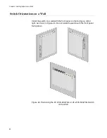
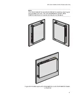
Refer to Figure 29 on page 76. For the AT
-
x530
-
28GPXm or AT-x530-
52GPXm switch, install four wall/equipment rack brackets to the sides
of the unit with the 16 M4x6mm screws included with the switch. Refer
Note
The AT
-
x530
-
28GPXm and AT-x530-52GPXm switch requires four
brackets to be installed due to its weight. Whereas, the
AT
-
x530
-
28GTXm and AT-x530-52GTXm only requires two
brackets because it is lighter.
Summary of Contents for AlliedWare Plus AT-x530 Series
Page 10: ...Tables 10...
Page 14: ...Preface 14...
Page 58: ...Chapter 3 Installing the Switch on a Table 58...
Page 90: ...Chapter 6 Powering On the Switch 90...


