7
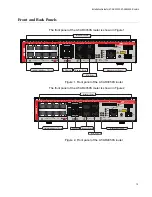
Figure 1: Front panel of the AT-AR3050S router..................................................................................................................19
Figure 2: Front panel of the AT-AR4050S router..................................................................................................................19
Figure 3: Back panel of the AT-AR3050S and AT-AR4050S routers ...................................................................................20
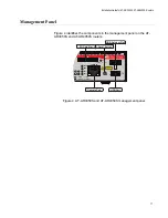
Figure 4: AT-AR3050S and AT-AR4050S management panel ............................................................................................21
Figure 5: Power LED ............................................................................................................................................................26
Figure 6: Fault LED ..............................................................................................................................................................27
Figure 7: HA LED .................................................................................................................................................................27
Figure 8: USB LED ...............................................................................................................................................................28
Figure 9: SD Card LED.........................................................................................................................................................29
Figure 10: ETH Port (RJ-45) LEDs .......................................................................................................................................30
Figure 11: LEDs for the 10/100/1000Base-T Ports...............................................................................................................32
Figure 12: LEDs for ETH 1 and ETH 2 Ports (SFP) .............................................................................................................33
Figure 13: Function 1 LED....................................................................................................................................................34
Figure 14: Function 2 LED....................................................................................................................................................34
Figure 15: USB port..............................................................................................................................................................35
Figure 16: USB retainer slot .................................................................................................................................................36
Figure 17: USB retainer ........................................................................................................................................................37
Figure 18: Attaching the USB retainer ..................................................................................................................................37
Figure 19: Attaching the cable tie .........................................................................................................................................38
Figure 20: SD card slot.........................................................................................................................................................39
Figure 21: Console port ........................................................................................................................................................40
Figure 22: Reset button ........................................................................................................................................................41
Figure 23: Components of the AT-AR3050S and AT-AR4050S routers...............................................................................49
Figure 24: Power cord retaining clip .....................................................................................................................................52
Figure 25: Inserting the retaining clip into the retaining bracket ...........................................................................................52
Figure 26: Attaching the rubber feet .....................................................................................................................................54
Figure 27: Turning the router upside down...........................................................................................................................55
Figure 28: Removing the rubber feet ....................................................................................................................................56
Figure 29: Attaching handles to the brackets .......................................................................................................................56
Figure 30: Attaching the equipment rack brackets ...............................................................................................................57
Figure 31: Mounting the router horizontally in an equipment rack........................................................................................57
Figure 32: Attaching the wall mount brackets to the side of the router.................................................................................59
Figure 33: Making the anchor hole locations........................................................................................................................60
Figure 34: Securing the router to the wall.............................................................................................................................61
Figure 35: Power cord retaining clip in the up position.........................................................................................................62
Figure 36: Connecting the AC power cord............................................................................................................................63
Figure 37: Connecting the Management Cable to the Console Port ....................................................................................64
Figure 38: Router initialization messages.............................................................................................................................65
Figure 39: Router initialization messages (Continued) .........................................................................................................66
Figure 40: Removing the dust plug from an SFP slot ...........................................................................................................70
Figure 41: Installing an SFP transceiver...............................................................................................................................71
Figure 42: Removing the dust cover from an SFP transceiver .............................................................................................71
Figure 43: Positioning the SFP handle in the upright position..............................................................................................72
Figure 44: Connecting a fiber optic cable to an SFP transceiver..........................................................................................72
Figure 45: RJ-45 Socket Pin Layout (Front View) ................................................................................................................79
Figures
Summary of Contents for AT-AR3050S
Page 8: ...Figures 8 ...
Page 10: ...Tables 10 ...
Page 14: ...Preface 12 ...
Page 50: ...Chapter 2 Beginning the Installation 16 ...
Page 76: ...Chapter 5 Troubleshooting 40 ...


