AT-DC2552XS / L3 Enterprise Core Switch Installation Guide
93
Console Port Pinouts
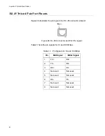
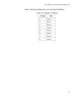
Figure 45 illustrates the pin locations of the USB Console connector.
Figure 45. USB Console Connector and Port Pin Layout
Table 16 lists the pinout functions for the Console port connector.
Table 16. Console Pinouts
Pinout
Signal
1
RTS (RS)
2
RXD (RD
3
TXD (SD)
4
CTS (CS)
5
NOT USED
6
NOT USED
7
NOT USED
1
RTS (RS)
Summary of Contents for AT-DC2552XS
Page 1: ...613 002097 Rev A AT DC2552XS L3 ENTERPRISE CORE SWITCH Installation Guide...
Page 8: ...Figures 8...
Page 10: ...Tables 10...
Page 14: ...Preface 14...
Page 34: ...Chapter 1 Overview 34...
Page 44: ...Chapter 2 VCStack Overview 44...
Page 86: ...Chapter 7 Managing the Switch 86...
Page 90: ...Chapter 8 Troubleshooting 90...

