AT-SBx908 GEN2 Installation Guide for Virtual Chassis Stacking
129
Figure 85. Removing the Terminal Screws
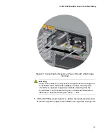
6. With a #3 Phillips-head screwdriver, connect the positive (+) power
lead wire to the positive terminal on the power supply, with one of the
terminal screws removed in the previous step. The positive terminal is
on the left. Refer to Figure 86 on page 130.
Allied Telesis recommends tightening the screw to 30 to 40 inch-lbs.
Summary of Contents for AT-FAN08
Page 10: ...Figures 10...
Page 12: ...Tables 12...
Page 16: ...Preface 16...
Page 38: ...Chapter 1 Overview 38...
Page 60: ...Chapter 2 Virtual Chassis Stacking 60...
Page 82: ...Chapter 4 Installing the Chassis 82 Figure 34 Example of Adjusting the Equipment Rack Brackets...
Page 104: ...Chapter 4 Installing the Chassis 104...
Page 140: ...Chapter 5 Powering On the Chassis 140...
Page 166: ...Chapter 7 Cabling the AT XEM2 Line Card Ports 166...


