Chapter 6: Configuring Switches for Stacking
148
Verifying the Switch with AlliedWare Plus Commands
Now that you have installed the switch and powered it on for the first time,
you should verify that the hardware components are operating normally.
The following procedure show how to do this using commands in the
AlliedWare Plus operating system. To verify the hardware operations of
the switch, perform the following procedure:
1. Start a local management session on the switch. Refer to “Starting a
Local Management Session” on page 145.
2. To display the status of the power supplies and fan modules, enter the
SHOW SYSTEM ENVIRONMENT command in the User Exec or
Privileged Exec mode. The Status column in the display provides the
states of the modules. Components are operating normally when they
have an “Ok” status.
The next command, SHOW CARD, has to be performed from the
Privileged Exec mode. If you are still in the User Exec mode, enter the
ENABLE command to move to the Privileged Exec mode. The mode
prompt is “awplus#”.
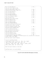
3. To display the status of the line cards, enter the SHOW CARD
command in the Privileged Exec mode. Line cards are operating
normally when their status are “Online.” Figure 97 is an example.
Figure 97. SHOW CARD Command
4. To display the states of the individual ports on the Ethernet line cards,
use the SHOW INTERFACE STATUS command in the Privileged
Exec mode.
For information about the command line interface, refer to the
Software Reference for SwitchBlade x908 GEN2 Series Switches on
the Allied Telesis web site.
5. Go to “Viewing the AlliedWare Plus Version Number” on page 149.
awplus# show card
Slot
Card Type
State
---------------------------------------------------
1
AT-XEM2-12XT
Online
2
AT-XEM2-12XT
Online
3
AT-XEM2-12XT
Online
4
AT-XEM2-12XS
Online
5
AT-XEM2-12XS
Online
6
AT-XEM2-1CQ
Online
7
AT-XEM2-4QS
Online
8
AT-XEM2-4QS
Online
Summary of Contents for AT-FAN08
Page 10: ...Figures 10...
Page 12: ...Tables 12...
Page 16: ...Preface 16...
Page 38: ...Chapter 1 Overview 38...
Page 60: ...Chapter 2 Virtual Chassis Stacking 60...
Page 82: ...Chapter 4 Installing the Chassis 82 Figure 34 Example of Adjusting the Equipment Rack Brackets...
Page 104: ...Chapter 4 Installing the Chassis 104...
Page 140: ...Chapter 5 Powering On the Chassis 140...
Page 166: ...Chapter 7 Cabling the AT XEM2 Line Card Ports 166...


