AT-SBx908 GEN2 Installation Guide for Virtual Chassis Stacking
173
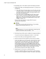
supply. (If you have not yet wired the DC connector on the power
supply, refer to “Powering On AT-SBxPWRSYS1-80 DC Power
Supplies” on page 110.)
Refer to “Power Specifications” on page 209 for the power
specifications of the switches.
Warning
Power cord is used as a disconnection device. To de-energize
equipment, disconnect the power cord.
E3
Note
Pluggable Equipment. The socket outlet shall be installed near the
equipment and shall be easily accessible.
E5
2. Wait four minutes for the switches to select a master switch and to
assign the ID numbers.
At this point, the stack is operational. The ID numbers are
automatically stored in special files in the flash memories of the
switches and are retained by the devices even when you reset or
power cycle the stack.
3. To continue with the installation, go to “Verifying the Stack” on
Summary of Contents for AT-FAN08
Page 10: ...Figures 10...
Page 12: ...Tables 12...
Page 16: ...Preface 16...
Page 38: ...Chapter 1 Overview 38...
Page 60: ...Chapter 2 Virtual Chassis Stacking 60...
Page 82: ...Chapter 4 Installing the Chassis 82 Figure 34 Example of Adjusting the Equipment Rack Brackets...
Page 104: ...Chapter 4 Installing the Chassis 104...
Page 140: ...Chapter 5 Powering On the Chassis 140...
Page 166: ...Chapter 7 Cabling the AT XEM2 Line Card Ports 166...


